Installation and Configuration
Configure for Multichannel Operation
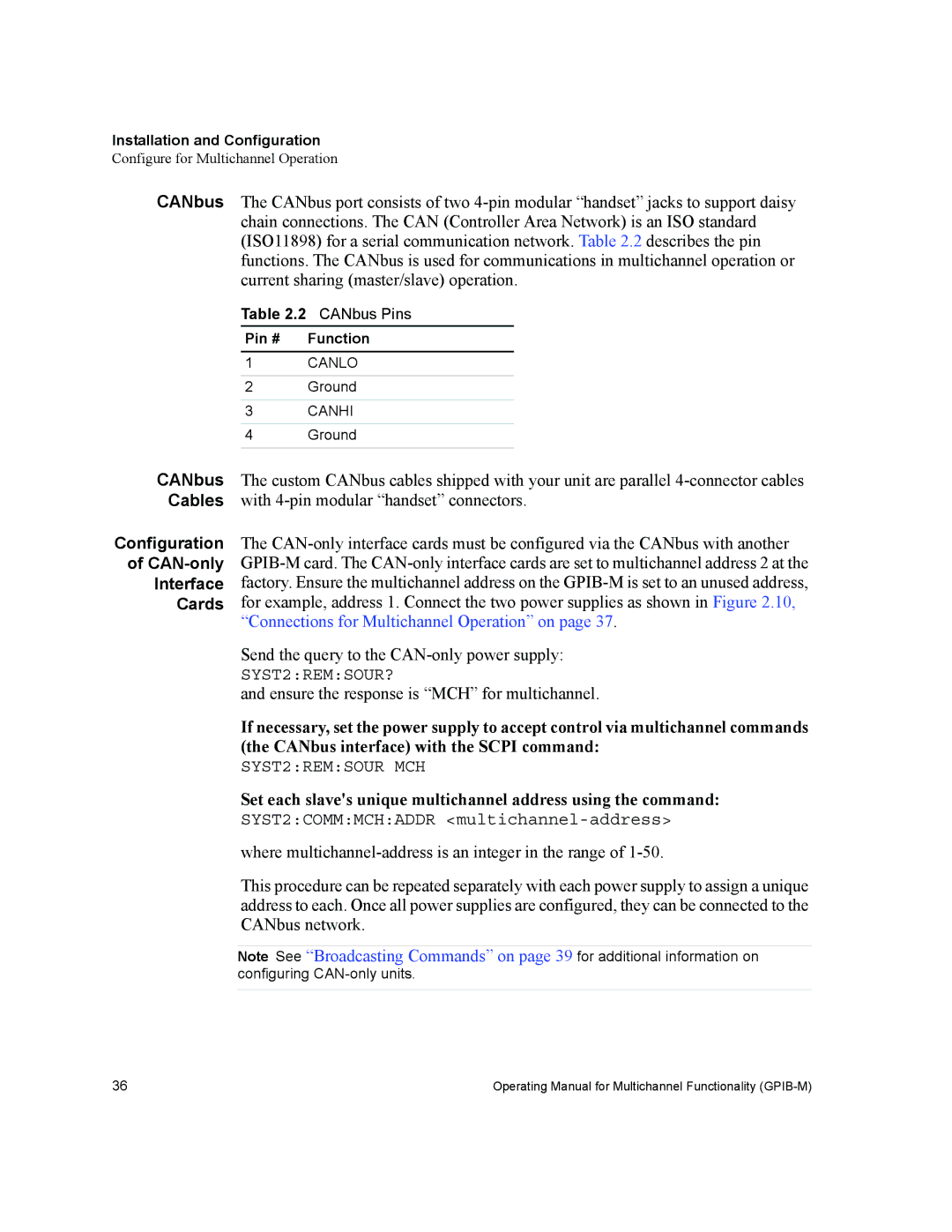
CANbus The CANbus port consists of two
Table 2.2 CANbus Pins
Pin # | Function |
1CANLO
2Ground
3CANHI
4Ground
CANbus | The custom CANbus cables shipped with your unit are parallel |
Cables | with |
Configuration | The |
of | |
Interface | factory. Ensure the multichannel address on the |
Cards | for example, address 1. Connect the two power supplies as shown in Figure 2.10, |
| “Connections for Multichannel Operation” on page 37. |
| Send the query to the |
| SYST2:REM:SOUR? |
| and ensure the response is “MCH” for multichannel. |
| If necessary, set the power supply to accept control via multichannel commands |
| (the CANbus interface) with the SCPI command: |
| SYST2:REM:SOUR MCH |
| Set each slave's unique multichannel address using the command: |
| SYST2:COMM:MCH:ADDR |
| where |
| This procedure can be repeated separately with each power supply to assign a unique |
| address to each. Once all power supplies are configured, they can be connected to the |
| CANbus network. |
|
|
| Note See “Broadcasting Commands” on page 39 for additional information on |
| configuring |
|
|
36 | Operating Manual for Multichannel Functionality |