Status Registers
Overview
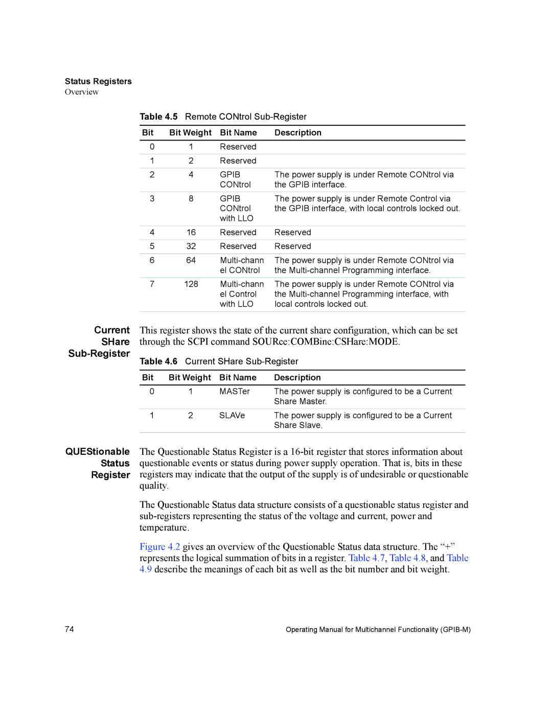
Table 4.5 Remote CONtrol
Bit | Bit Weight | Bit Name | Description |
0 | 1 | Reserved |
|
|
|
|
|
1 | 2 | Reserved |
|
|
|
|
|
2 | 4 | GPIB | The power supply is under Remote CONtrol via |
|
| CONtrol | the GPIB interface. |
|
|
|
|
3 | 8 | GPIB | The power supply is under Remote Control via |
|
| CONtrol | the GPIB interface, with local controls locked out. |
|
| with LLO |
|
|
|
|
|
4 | 16 | Reserved | Reserved |
|
|
|
|
5 | 32 | Reserved | Reserved |
|
|
|
|
6 | 64 | The power supply is under Remote CONtrol via | |
|
| el CONtrol | the |
7 | 128 | The power supply is under Remote CONtrol via | |
|
| el Control | the |
|
| with LLO | local controls locked out. |
Current | This register shows the state of the current share configuration, which can be set | |||
SHare | through the SCPI command SOURce:COMBine:CSHare:MODE. | |||
| Table 4.6 Current SHare | |||
|
|
|
|
|
| Bit | Bit Weight | Bit Name | Description |
|
|
|
|
|
| 0 | 1 | MASTer | The power supply is configured to be a Current |
|
|
|
| Share Master. |
| 1 | 2 | SLAVe | The power supply is configured to be a Current |
|
|
|
| Share Slave. |
|
|
|
|
|
QUEStionable The Questionable Status Register is a
Register registers may indicate that the output of the supply is of undesirable or questionable quality.
The Questionable Status data structure consists of a questionable status register and
Figure 4.2 gives an overview of the Questionable Status data structure. The “+” represents the logical summation of bits in a register. Table 4.7, Table 4.8, and Table
4.9describe the meanings of each bit as well as the bit number and bit weight.
74 | Operating Manual for Multichannel Functionality |