Controller components and options
1
2
3
4
5
6
7
8
9
10
11
12
13
14
15
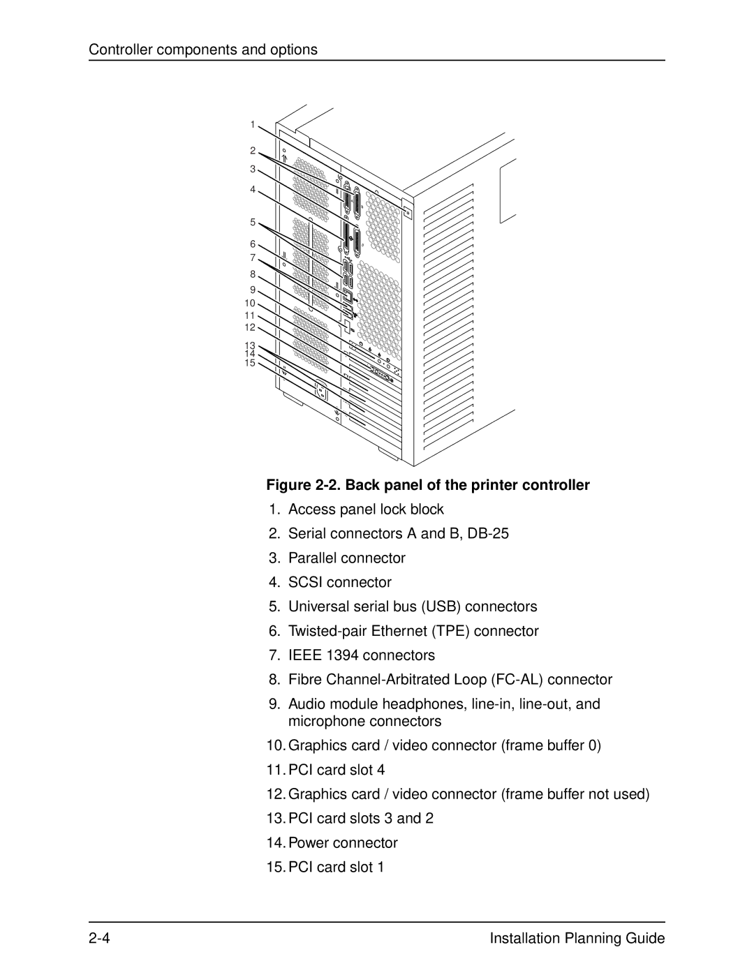
Figure 2-2. Back panel of the printer controller
1.Access panel lock block
2.Serial connectors A and B,
3.Parallel connector
4.SCSI connector
5.Universal serial bus (USB) connectors
6.
7.IEEE 1394 connectors
8.Fibre
9.Audio module headphones,
10.Graphics card / video connector (frame buffer 0)
11.PCI card slot 4
12.Graphics card / video connector (frame buffer not used)
13.PCI card slots 3 and 2
14.Power connector
15.PCI card slot 1
Installation Planning Guide |