Installation
Defining a Frequency Plan
gy D5 | Oy”p•— ly | ||
| ,Store- vp | Cell Site y±xmp• | |
gy E5 | Oq z± ©t”s | qz• plns | |
Qyzyy– u dP
dz± xl
fyyy
❏F WH
❏F WH “•zr•lx qz•
❏F y±ww xzopx nlmwp qz•
❏Optional – An initialized SRAM card for storing the frequency plans once defined.
hy gy dP Pyw
If you have not done so already, configure the PC to communicate with the Test Set (see “Configuring the Test Set and PC Serial Ports for Communication with the Test Set” on page 28).
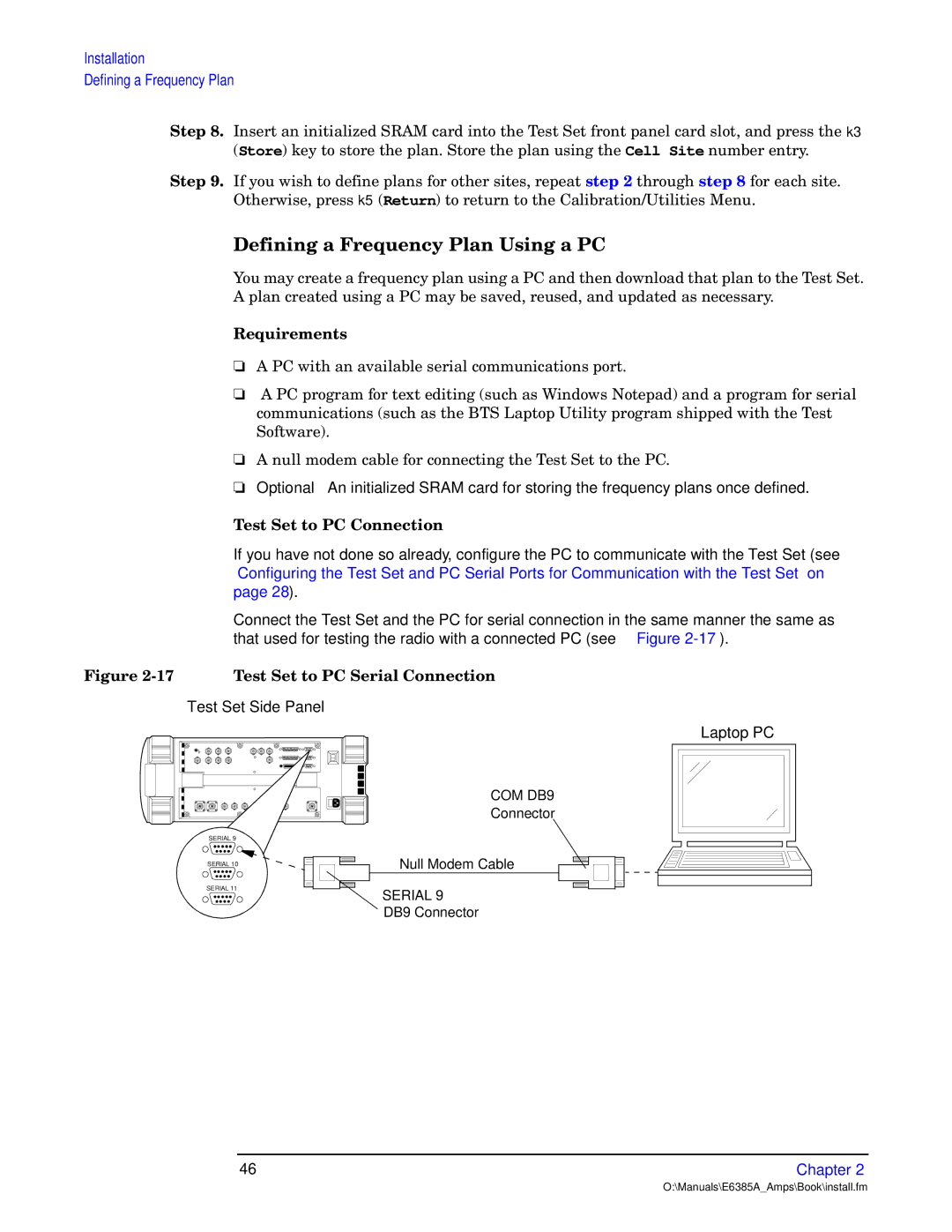
Connect the Test Set and the PC for serial connection in the same manner the same as that used for testing the radio with a connected PC (see Figure
S 948C | hy gy y P |
Test Set Side Panel
SERIAL 9
SERIAL 10
SERIAL 11
Laptop PC
COM DB9
Connector
Null Modem Cable
SERIAL 9
DB9 Connector
46 | Chapter 2 |
O:\Manuals\E6385A_Amps\Book\install.fm