Installation
Connecting the PC to the Test Set and the MSC
Ouzw bO zw fwws w YeO
]tq r“xx“uzs —qo±u“z— pq—o”unq ±tq –”“oq——q— r“” o“zzqo±uzs ±tq XK ±“ n“±t ±tq ]q—± [q± mzp ±tq U[K4
| Owuy zw bO zw fw ew |
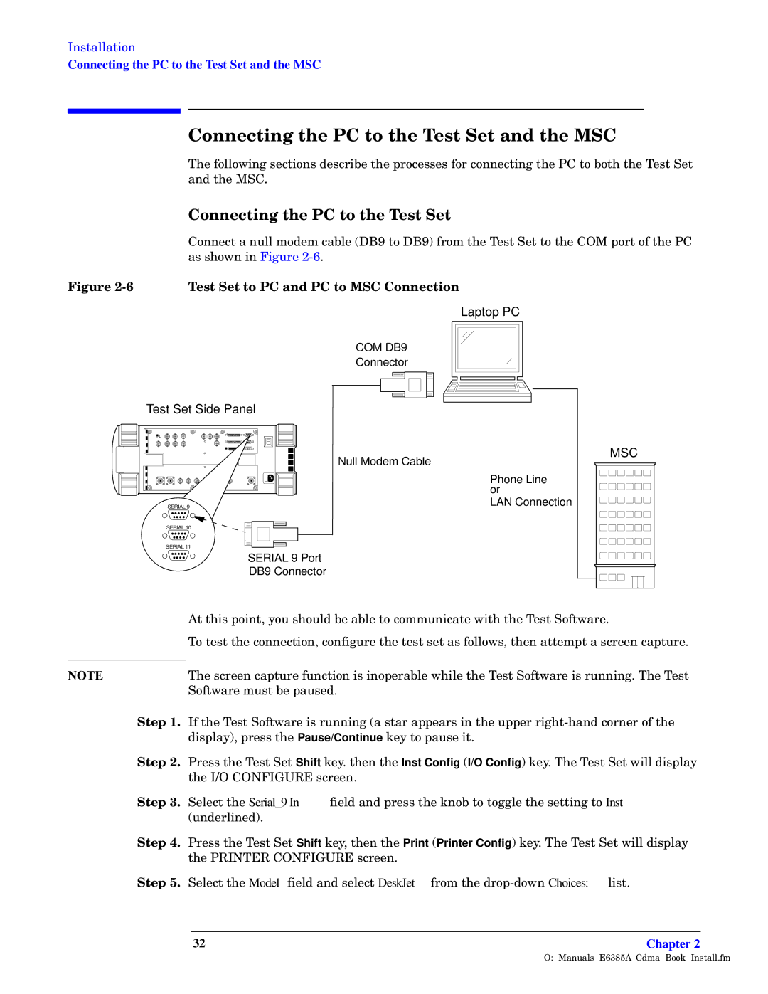
| K“zzqo± m z®xx y“pqy omnxq .LJA ±“ LJA/ r”“y ±tq ]q—± [q± ±“ ±tq KWU –“”± “r ±tq XK |
| m— —t“z uz Nus®”q 83=4 |
R–y 83A | fw ew bO sv bO YeO Owu– |
| | | | | | | | | | | | | Laptop PC |
| | | | | | | | | | | | | | | | |
| | COM DB9 | | | | | | |
| | | | | | | |
| | | | | | | |
| | Connector | | | | | | |
| | | | | | | | | | | | | | | | | |
| | | | | | | | | | | | | | | | | |
| | | | | | | | | | | | | | | | | |
Test Set Side Panel
| Null Modem Cable |
| Phone Line |
| or |
SERIAL 9 | LAN Connection |
SERIAL 10 | |
SERIAL 11 | |
| SERIAL 9 Port |
| DB9 Connector |
MSC
| I± ±tu— –“uz±2 ® —t“®xp nq mnxq ±“ o“yy®zuom±q ±t ±tq ]q—± [“r±m”q4 |
| ]“ ±q—± ±tq o“zzqo±u“z2 o“zrus®”q ±tq ±q—± —q± m— r“xx“—2 ±tqz m±±qy–± m —o”qqz om–±®”q4 |
| ]tq —o”qqz om–±®”q r®zo±u“z u— uz“–q”mnxq uxq ±tq ]q—± [“r±m”q u— ”®zzuzs4 ]tq ]q—± |
NOTE |
| [“r±m”q y®—± nq –m®—qp4 |
ew 74 Qr ±tq ]q—± [“r±m”q u— ”®zzuzs .m —±m” m––qm”— uz ±tq ®––q” ”ust±3tmzp o“”zq” “r ±tq |
| pu—–xm2 –”q—— ±tq Pause/Continue wq±“ –m®—q u±4 |
ew 84 | X”q—— ±tq ]q—± [q± Shift wq4 ±tqz ±tq Inst Config .I/O Config/ wq4 ]tq ]q—± [q± uxx pu—–xm |
| ±tq Q5W KWVNQOaZM —o”qqz4 |
ew 94 | [qxqo± ±tq Serial_9 In ruqxp mzp –”q—— ±tq wz“n ±“ ±“ssxq ±tq —q±±uzs ±“ Inst |
| .®zpq”xuzqp/4 |
ew :4 | X”q—— ±tq ]q—± [q± Shift wq2 ±tqz ±tq Print .Printer Config/ wq4 ]tq ]q—± [q± uxx pu—–xm |
| ±tq XZQV]MZ KWVNQOaZM —o”qqz4 |
ew ?4 | [qxqo± ±tq Model ruqxp mzp —qxqo± DeskJet r”“y ±tq p”“–3p“ Choices: xu—±4 |
O:\Manuals\E6385A_Cdma\Book\Install.fm