Connections
Test Set to GPS Time and Frequency Reference Receiver Connections
fw ew Sbe f–Rwdwxww dwuw– Ou
Nus®”q 93;
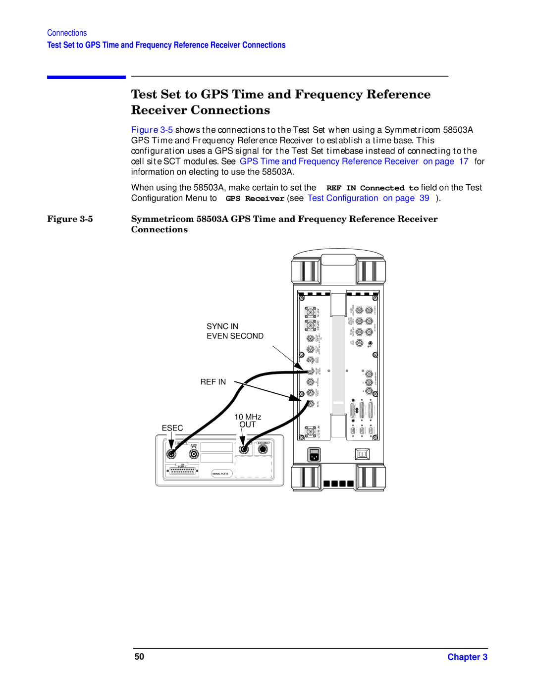
When using the 58503A, make certain to set the REF IN Connected to field on the Test Configuration Menu to GPS Receiver (see “Test Configuration” on page 39).
R–yw 93? ew–uM Sbe f– Rwwww dwuw–
Owu–
SYNC IN
EVEN SECOND
REF IN
| ANT IN | |
| DUPLEX | |
MHz OUT | 19.6608 | 16X CHIP CLOCK |
MHz OUT | 1.2288 | CHIP CLOCK |
CLOCK | FRAME |
|
SECOND | EVEN | SYNC IN |
IN | TRIG/QUAL |
|
REF OUT | 10 MHz |
|
| REF IN |
|
INPUT | MODULATION |
| AUDIO OUT |
MONITOR TRIG IN OUTPUT | AUDIO EXT SCOPE | HILO | AUDIO IN |
OUT | VIDEO |
|
|
|
| I | BASEBAND |
|
| Q | OUT |
|
| IN |
|
|
| P A | P A |
|
| R A | R A |
|
| L L | L L |
|
| E L | E L |
|
| P O | P O |
ESEC
Alarm |
(TTL) |
I/O |
PORT 1 |
10 MHz
OUT
10 MHz | ANTENNA |
SERIAL PLATE
RF IN/OUT |
| R T | R T |
S E R | S E R | S E R |
I A | I A | I A |
P O R T | P O R T | P O R T |
50 | Chapter 3 |