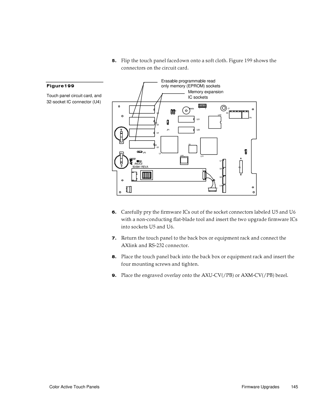
Figure199
Touch panel circuit card, and 32-socket IC connector (U4)
5.Flip the touch panel facedown onto a soft cloth. Figure 199 shows the connectors on the circuit card.
Erasable programmable read only memory (EPROM) sockets
Memory expansion IC sockets
| JP3JP2 | SPKR1 | 1 | 5 |
| J1 |
|
|
|
|
|
| |
| U3 |
|
|
| U19 | P3 |
|
|
|
|
|
| |
|
|
| U21 |
|
| P4 |
|
|
|
|
|
| |
| ODD |
|
|
|
|
|
| U6 |
|
|
|
|
|
| JP1 |
| U20 |
|
|
|
| U4 |
|
|
|
|
|
| EVEN | Y3 |
|
|
|
|
| U5 |
|
|
|
|
|
|
|
|
|
|
| JP6 |
JP5 | U1 |
|
|
|
|
|
|
|
|
|
|
| |
| U22 |
|
| U11 |
|
|
CORP. |
|
|
|
| U7 |
|
1996 |
|
|
|
|
| |
|
|
|
|
|
| |
|
|
|
| U9 | P5 | |
|
|
|
| 8 |
| |
|
|
|
|
|
| |
|
|
|
|
| U8 |
|
|
|
|
| 1 |
|
|
|
|
|
|
| U10 |
|
|
|
|
| 5 | 1 |
|
6.Carefully pry the firmware ICs out of the socket connectors labeled U5 and U6 with a
7.Return the touch panel to the back box or equipment rack and connect the AXlink and
8.Place the touch panel back into the back box or equipment rack and insert the four mounting screws and tighten.
9.Place the engraved overlay onto the
Color Active Touch Panels | Firmware Upgrades | 145 |