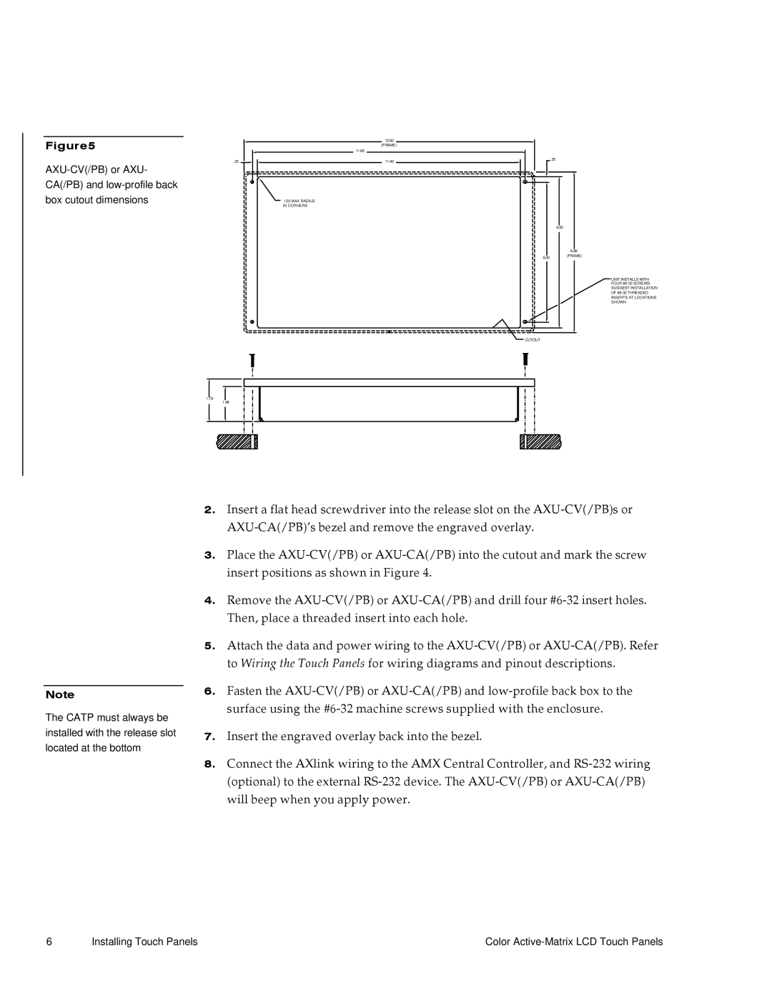
Figure5

.23

AXU-CV(/PB) or AXU- CA(/PB) and low-profile back box cutout dimensions

1.79

1.48

12.60

(FRAME)

11.85

11.40

.125 MAX RADIUS

IN CORNERS

.25

6.50

6.88

6.00(FRAME)

UNIT INSTALLS WITH

FOUR #6-32 SCREWS.

SUGGEST INSTALLATION

OF #6-32 THREADED

INSERTS AT LOCATIONS

SHOWN

CUTOUT

INSTALLATION METHOD

USE WHEN INSTALLING UNIT ON SOLID

SURFACES (PODIUM, DESK ETC.). FACE

FRAME AND LOW PROFILE BACKBOX

INSTALLED AS SINGLE "DROP-IN"

ASSEMBLY.

Note

The CATP must always be installed with the release slot located at the bottom

2.Insert a flat head screwdriver into the release slot on the AXU-CV(/PB)s or AXU-CA(/PB)’s bezel and remove the engraved overlay.

3.Place the AXU-CV(/PB) or AXU-CA(/PB) into the cutout and mark the screw insert positions as shown in Figure 4.

4.Remove the AXU-CV(/PB) or AXU-CA(/PB) and drill four #6-32 insert holes. Then, place a threaded insert into each hole.

5.Attach the data and power wiring to the AXU-CV(/PB) or AXU-CA(/PB). Refer to Wiring the Touch Panels for wiring diagrams and pinout descriptions.

6.Fasten the AXU-CV(/PB) or AXU-CA(/PB) and low-profile back box to the surface using the #6-32 machine screws supplied with the enclosure.

7.Insert the engraved overlay back into the bezel.

8.Connect the AXlink wiring to the AMX Central Controller, and RS-232 wiring (optional) to the external RS-232 device. The AXU-CV(/PB) or AXU-CA(/PB) will beep when you apply power.

6

Installing Touch Panels

Color Active-Matrix LCD Touch Panels

Page 14
Image 14
AMX G3 manual Installing Touch Panels Color Active-Matrix LCD Touch Panels