Hardware Reference
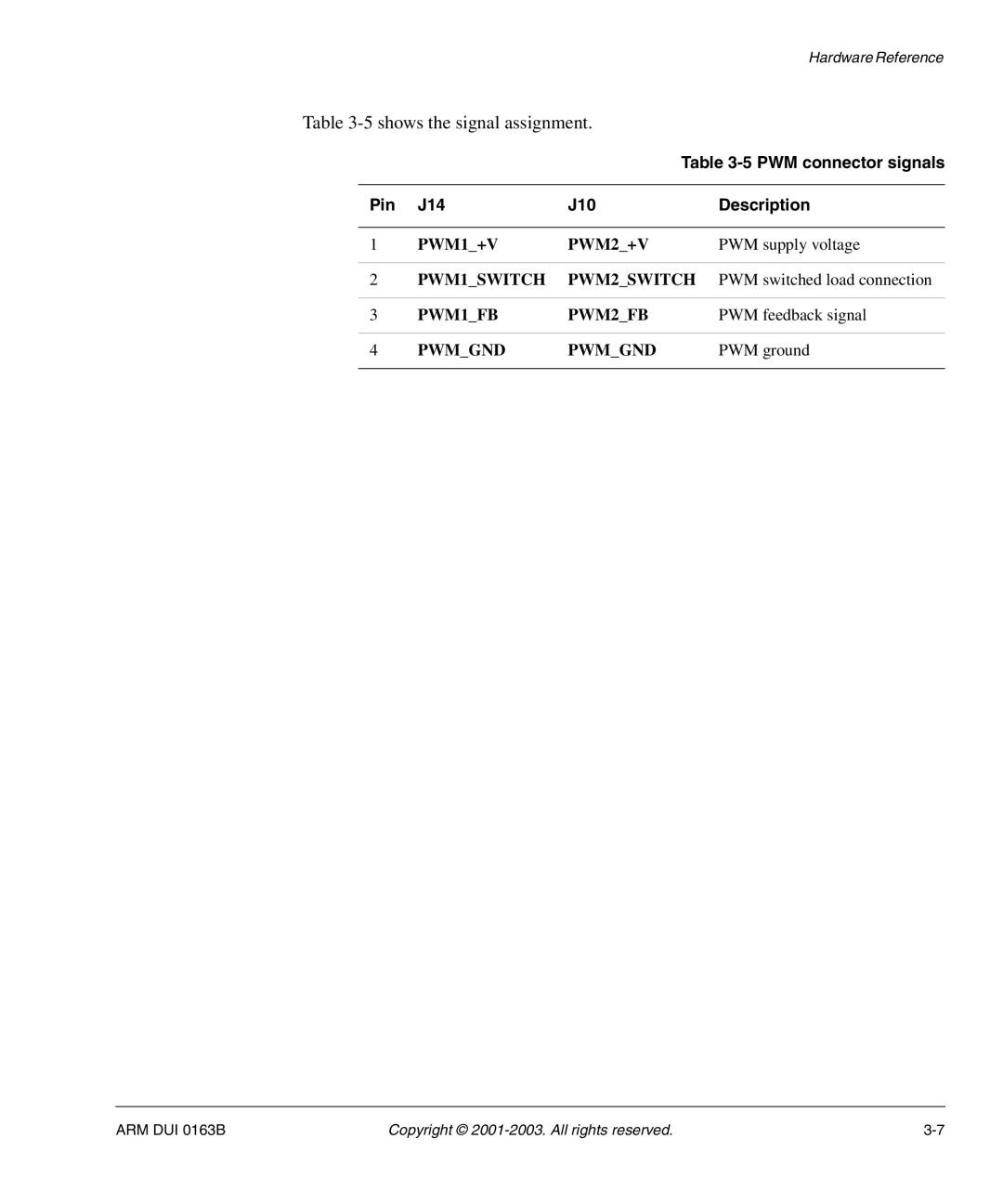
Table 3-5 shows the signal assignment.
Table 3-5 PWM connector signals
Pin | J14 | J10 | Description |
|
|
|
|
1 | PWM1_+V | PWM2_+V | PWM supply voltage |
|
|
|
|
2 | PWM1_SWITCH | PWM2_SWITCH | PWM switched load connection |
|
|
|
|
3 | PWM1_FB | PWM2_FB | PWM feedback signal |
|
|
|
|
4 | PWM_GND | PWM_GND | PWM ground |
|
|
|
|
ARM DUI 0163B | Copyright © |
