Reference Design Example
4.2.2Oscillator lock register
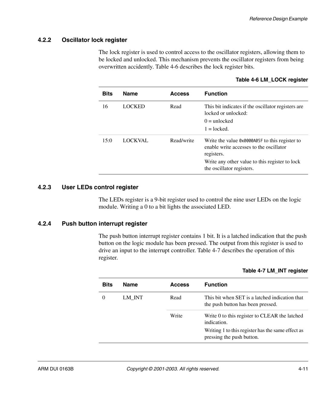
The lock register is used to control access to the oscillator registers, allowing them to be locked and unlocked. This mechanism prevents the oscillator registers from being overwritten accidently. Table
|
|
|
| Table |
|
|
|
| |
Bits | Name | Access | Function | |
|
|
|
| |
16 | LOCKED | Read | This bit indicates if the oscillator registers are | |
|
|
| locked or unlocked: | |
|
|
| 0 | = unlocked |
|
|
| 1 | = locked. |
|
|
|
| |
15:0 | LOCKVAL | Read/write | Write the value 0x0000A05F to this register to | |
|
|
| enable write accesses to the oscillator | |
|
|
| registers. | |
Write any other value to this register to lock the oscillator registers.
4.2.3User LEDs control register
The LEDs register is a
4.2.4Push button interrupt register
The push button interrupt register contains 1 bit. It is a latched indication that the push button on the logic module has been pressed. The output from this register is used to drive an input to the interrupt controller. Table
|
|
| Table |
|
|
|
|
Bits | Name | Access | Function |
|
|
|
|
0 | LM_INT | Read | This bit when SET is a latched indication that |
|
|
| the push button has been pressed. |
|
|
|
|
|
| Write | Write 0 to this register to CLEAR the latched |
|
|
| indication. |
|
|
| Writing 1 to this register has the same effect as |
|
|
| pressing the push button. |
|
|
|
|
ARM DUI 0163B | Copyright © |