|
|
| Reference Design Example |
|
| Table | |
|
|
|
|
Bits | Name | Access | Function |
|
|
|
|
2 | DOCOUNT | Read/write | Write a 1 to this bit to transfer the contents of the |
|
|
| buffer register to the count and speed registers. |
|
|
| This causes the corresponding number of steps |
|
|
| to be performed. |
|
|
|
|
1 | SINGLESTEP | Read/write | Write a 1 to this bit to advance the stepper motor |
|
|
| by one step. The step speed register, step count |
|
|
| register, and bit 2 are ignored. |
|
|
|
|
0 | DIR | Read/write | This bit controls the direction of rotation. The |
|
|
| actual direction of rotation (clockwise or |
|
|
| anticlockwise) depends on how the motor is |
|
|
| wired to the interface module. |
|
|
|
|
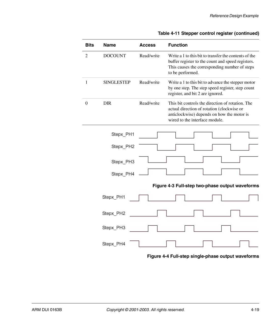
Stepx_PH1
Stepx_PH2
Stepx_PH3
Stepx_PH4
Figure 4-3 Full-step two-phase output waveforms
Stepx_PH1
Stepx_PH2
Stepx_PH3
Stepx_PH4
Figure 4-4 Full-step single-phase output waveforms
ARM DUI 0163B | Copyright © |