Reference Design Example
page
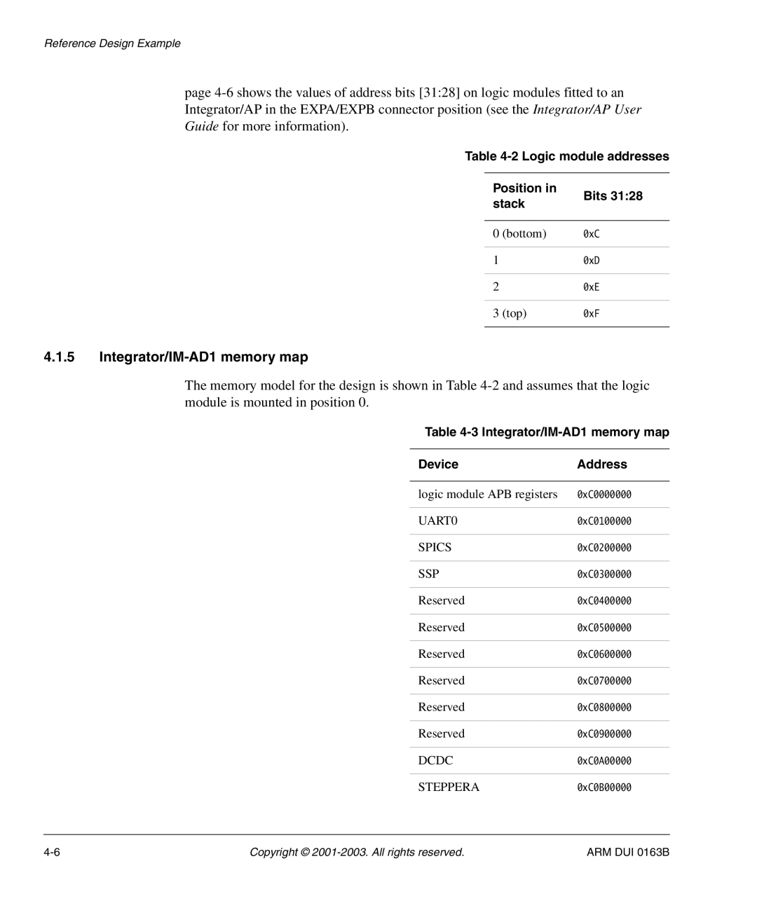
Table 4-2 Logic module addresses
Position in | Bits 31:28 | ||
stack | |||
| |||
|
|
| |
0 | (bottom) | 0xC | |
|
|
| |
1 |
| 0xD | |
|
|
| |
2 |
| 0xE | |
|
|
| |
3 | (top) | 0xF | |
|
|
| |
4.1.5Integrator/IM-AD1 memory map
The memory model for the design is shown in Table
Table 4-3 Integrator/IM-AD1 memory map
Device | Address |
|
|
logic module APB registers | 0xC0000000 |
|
|
UART0 | 0xC0100000 |
|
|
SPICS | 0xC0200000 |
|
|
SSP | 0xC0300000 |
|
|
Reserved | 0xC0400000 |
|
|
Reserved | 0xC0500000 |
|
|
Reserved | 0xC0600000 |
|
|
Reserved | 0xC0700000 |
|
|
Reserved | 0xC0800000 |
|
|
Reserved | 0xC0900000 |
|
|
DCDC | 0xC0A00000 |
|
|
STEPPERA | 0xC0B00000 |
Copyright © | ARM DUI 0163B |