Reference Design Example
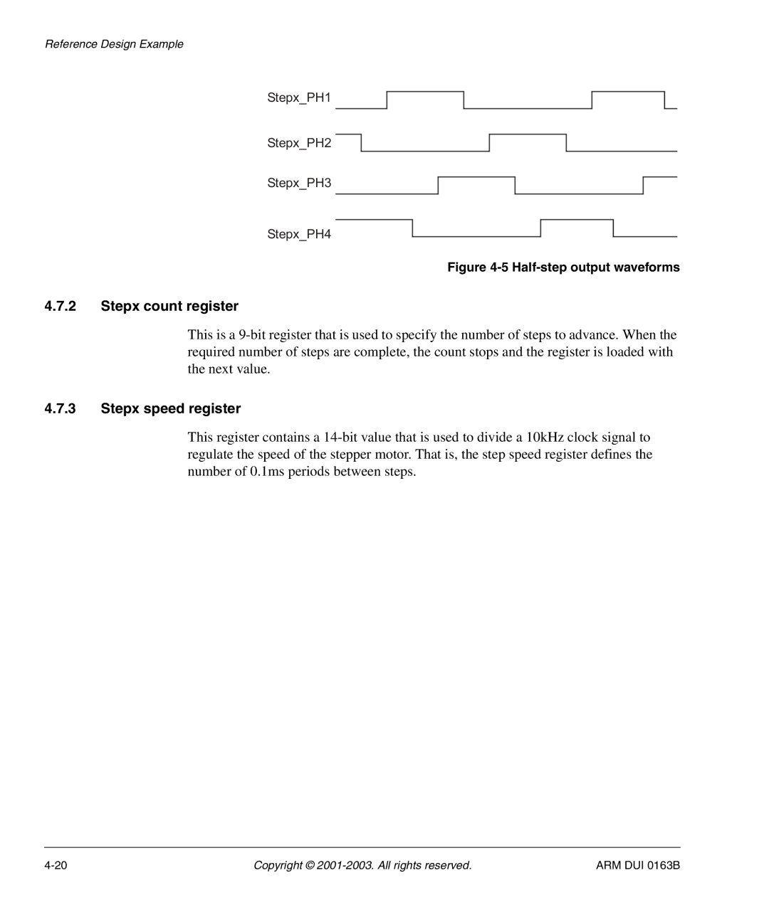
Stepx_PH1
Stepx_PH2
Stepx_PH3
Stepx_PH4
Figure 4-5 Half-step output waveforms
4.7.2Stepx count register
This is a 9-bit register that is used to specify the number of steps to advance. When the required number of steps are complete, the count stops and the register is loaded with the next value.
4.7.3Stepx speed register
This register contains a 14-bit value that is used to divide a 10kHz clock signal to regulate the speed of the stepper motor. That is, the step speed register defines the number of 0.1ms periods between steps.
4-20 | Copyright © 2001-2003. All rights reserved. | ARM DUI 0163B |