Reference Design Example
4.10Vectored interrupt controller
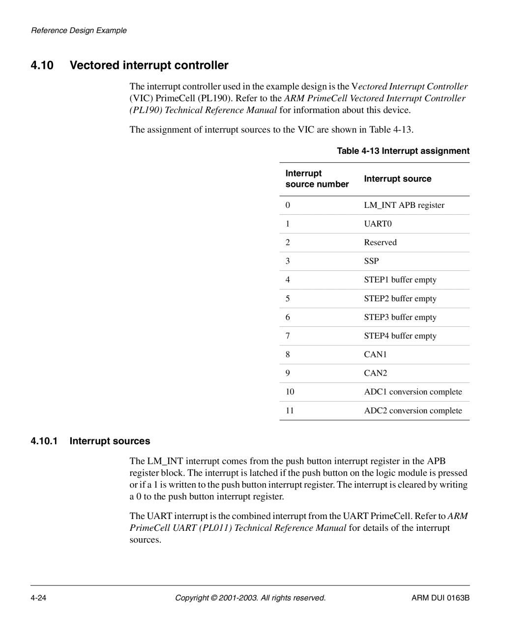
The interrupt controller used in the example design is the Vectored Interrupt Controller (VIC) PrimeCell (PL190). Refer to the ARM PrimeCell Vectored Interrupt Controller (PL190) Technical Reference Manual for information about this device.
The assignment of interrupt sources to the VIC are shown in Table
| Table | ||
|
|
| |
Interrupt |
| Interrupt source | |
source number | |||
| |||
|
|
| |
0 |
| LM_INT APB register | |
|
|
| |
1 |
| UART0 | |
|
|
| |
2 |
| Reserved | |
|
|
| |
3 |
| SSP | |
|
|
| |
4 |
| STEP1 buffer empty | |
|
|
| |
5 |
| STEP2 buffer empty | |
|
|
| |
6 |
| STEP3 buffer empty | |
|
|
| |
7 |
| STEP4 buffer empty | |
|
|
| |
8 |
| CAN1 | |
|
|
| |
9 |
| CAN2 | |
|
|
| |
10 |
| ADC1 conversion complete | |
|
|
| |
11 |
| ADC2 conversion complete | |
|
|
| |
4.10.1Interrupt sources
The LM_INT interrupt comes from the push button interrupt register in the APB register block. The interrupt is latched if the push button on the logic module is pressed or if a 1 is written to the push button interrupt register. The interrupt is cleared by writing a 0 to the push button interrupt register.
The UART interrupt is the combined interrupt from the UART PrimeCell. Refer to ARM PrimeCell UART (PL011) Technical Reference Manual for details of the interrupt sources.
Copyright © | ARM DUI 0163B |