Reference Design Example
4.11CAN controller interface
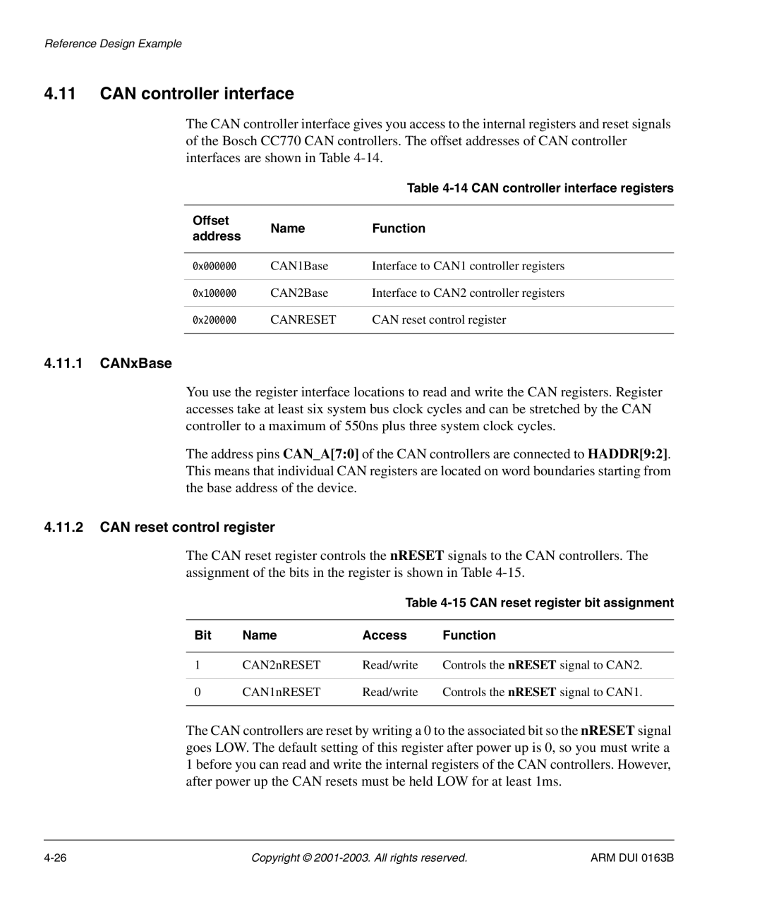
The CAN controller interface gives you access to the internal registers and reset signals of the Bosch CC770 CAN controllers. The offset addresses of CAN controller interfaces are shown in Table
|
| Table | |
|
|
| |
Offset | Name | Function | |
address | |||
|
| ||
|
|
| |
0x000000 | CAN1Base | Interface to CAN1 controller registers | |
|
|
| |
0x100000 | CAN2Base | Interface to CAN2 controller registers | |
|
|
| |
0x200000 | CANRESET | CAN reset control register | |
|
|
|
4.11.1CANxBase
You use the register interface locations to read and write the CAN registers. Register accesses take at least six system bus clock cycles and can be stretched by the CAN controller to a maximum of 550ns plus three system clock cycles.
The address pins CAN_A[7:0] of the CAN controllers are connected to HADDR[9:2]. This means that individual CAN registers are located on word boundaries starting from the base address of the device.
4.11.2CAN reset control register
The CAN reset register controls the nRESET signals to the CAN controllers. The assignment of the bits in the register is shown in Table
Table
Bit | Name | Access | Function |
|
|
|
|
1 | CAN2nRESET | Read/write | Controls the nRESET signal to CAN2. |
|
|
|
|
0 | CAN1nRESET | Read/write | Controls the nRESET signal to CAN1. |
|
|
|
|
The CAN controllers are reset by writing a 0 to the associated bit so the nRESET signal goes LOW. The default setting of this register after power up is 0, so you must write a 1 before you can read and write the internal registers of the CAN controllers. However, after power up the CAN resets must be held LOW for at least 1ms.
Copyright © | ARM DUI 0163B |