Hardware Reference
3.5Stepper motor interface
The
3and Step 4, provide
3.5.1Functional description
The
STEP1_VSS
| STEP1_ENA |
|
|
Socket | STEP1_ENB |
|
|
STEP1_PH2 |
|
| |
| STEP1_PH1 |
| L298 |
|
|
| |
IM | STEP1_PH3 | L6506 | (U24) |
(U23) |
| ||
| STEP1_PH4 |
| |
|
|
|
STEP1_O1
STEP1_O2
STEP1_O3
STEP1_O4
J19
motor | windings | |
Stepper | ||
|
STEP_GND
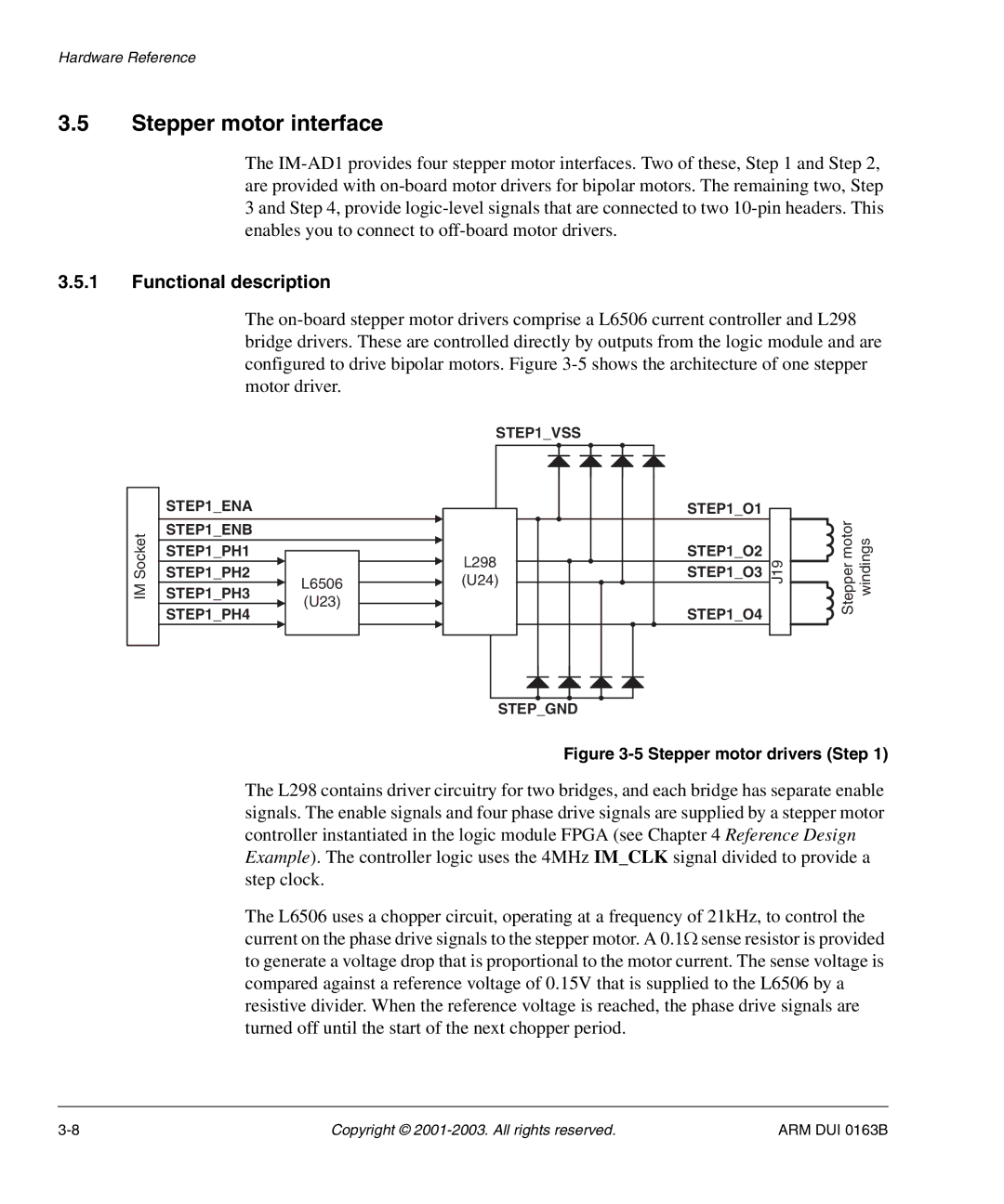
Figure 3-5 Stepper motor drivers (Step 1)
The L298 contains driver circuitry for two bridges, and each bridge has separate enable signals. The enable signals and four phase drive signals are supplied by a stepper motor controller instantiated in the logic module FPGA (see Chapter 4 Reference Design Example). The controller logic uses the 4MHz IM_CLK signal divided to provide a step clock.
The L6506 uses a chopper circuit, operating at a frequency of 21kHz, to control the current on the phase drive signals to the stepper motor. A 0.1Ω sense resistor is provided to generate a voltage drop that is proportional to the motor current. The sense voltage is compared against a reference voltage of 0.15V that is supplied to the L6506 by a resistive divider. When the reference voltage is reached, the phase drive signals are turned off until the start of the next chopper period.
Copyright © | ARM DUI 0163B |