Hardware Reference
Table 3-8 CAN interface signal assignment (continued)
Signal | EXPIM | Description | |
connector | |||
|
| ||
|
|
| |
CAN2_nINT | IM_BBANK28 | CAN2 interrupt | |
|
|
| |
CAN1_RXD | IM_BBANK29 | CAN1 receive data | |
|
|
| |
CAN2_RXD | IM_BBANK30 | CAN2 receive data | |
|
|
|
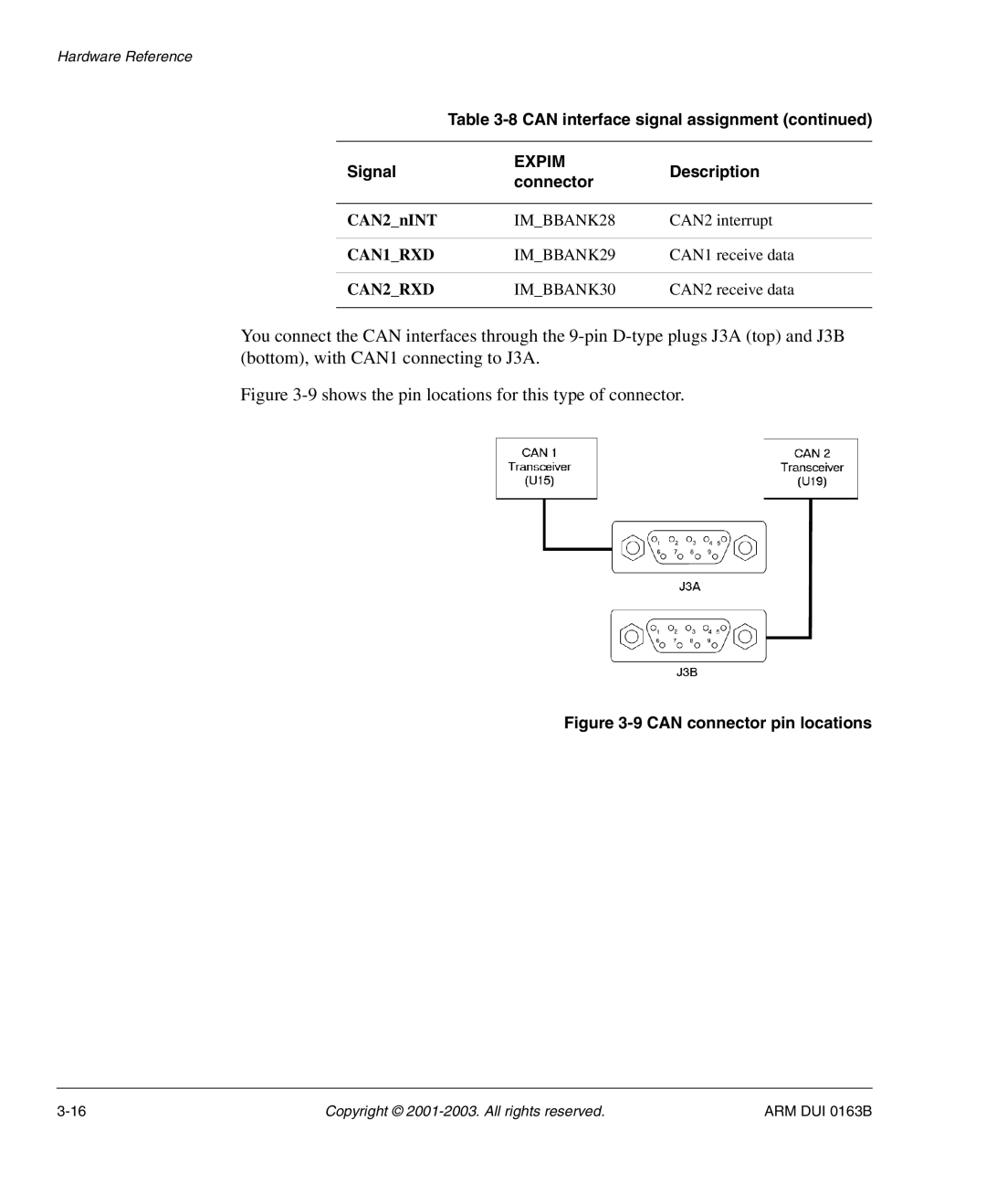
You connect the CAN interfaces through the
Figure 3-9 shows the pin locations for this type of connector.
Figure 3-9 CAN connector pin locations
Copyright © | ARM DUI 0163B |