Hardware Reference
Table
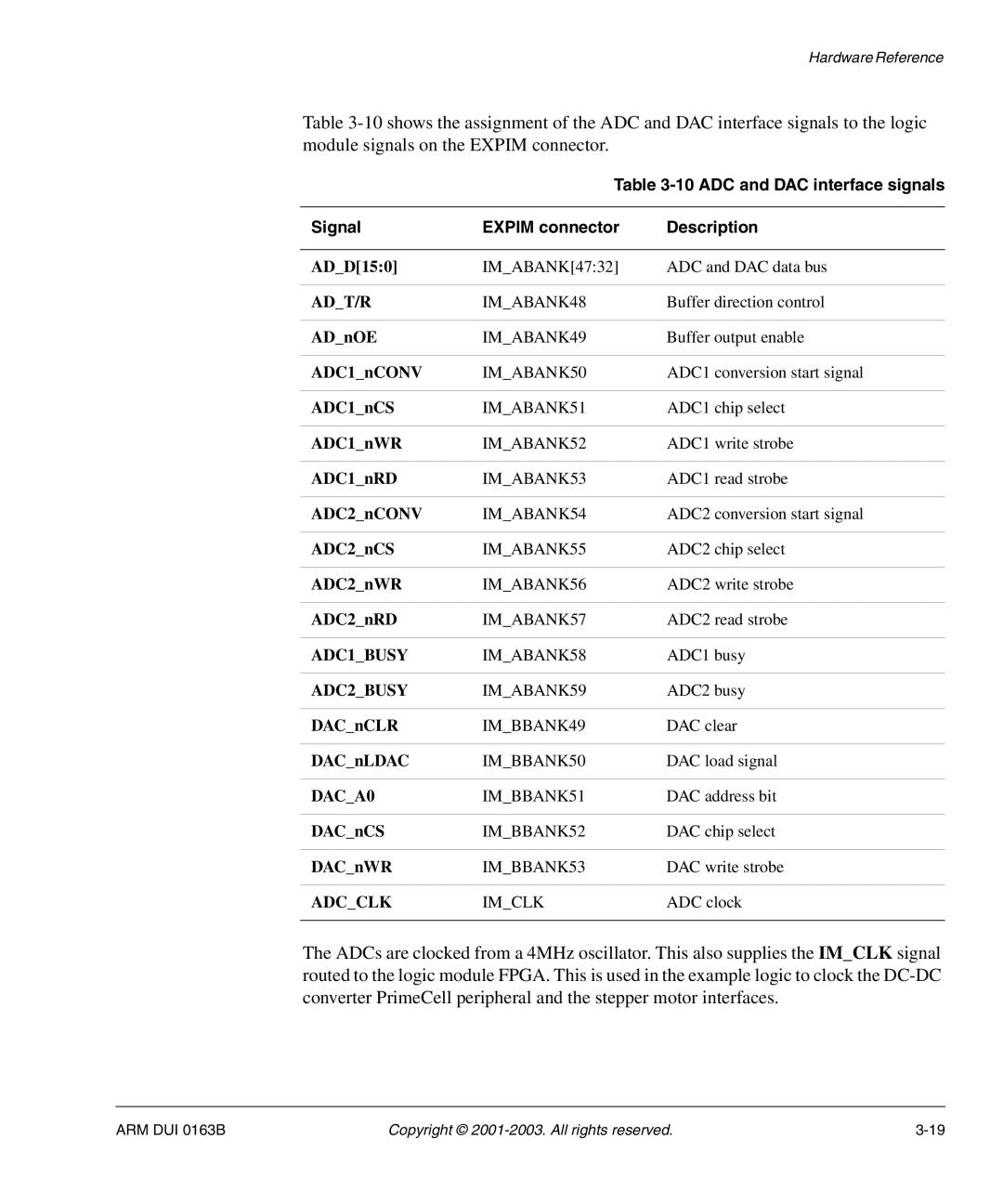
Table
Signal | EXPIM connector | Description |
|
|
|
AD_D[15:0] | IM_ABANK[47:32] | ADC and DAC data bus |
|
|
|
AD_T/R | IM_ABANK48 | Buffer direction control |
|
|
|
AD_nOE | IM_ABANK49 | Buffer output enable |
|
|
|
ADC1_nCONV | IM_ABANK50 | ADC1 conversion start signal |
|
|
|
ADC1_nCS | IM_ABANK51 | ADC1 chip select |
|
|
|
ADC1_nWR | IM_ABANK52 | ADC1 write strobe |
|
|
|
ADC1_nRD | IM_ABANK53 | ADC1 read strobe |
|
|
|
ADC2_nCONV | IM_ABANK54 | ADC2 conversion start signal |
|
|
|
ADC2_nCS | IM_ABANK55 | ADC2 chip select |
|
|
|
ADC2_nWR | IM_ABANK56 | ADC2 write strobe |
|
|
|
ADC2_nRD | IM_ABANK57 | ADC2 read strobe |
|
|
|
ADC1_BUSY | IM_ABANK58 | ADC1 busy |
|
|
|
ADC2_BUSY | IM_ABANK59 | ADC2 busy |
|
|
|
DAC_nCLR | IM_BBANK49 | DAC clear |
|
|
|
DAC_nLDAC | IM_BBANK50 | DAC load signal |
|
|
|
DAC_A0 | IM_BBANK51 | DAC address bit |
|
|
|
DAC_nCS | IM_BBANK52 | DAC chip select |
|
|
|
DAC_nWR | IM_BBANK53 | DAC write strobe |
|
|
|
ADC_CLK | IM_CLK | ADC clock |
|
|
|
The ADCs are clocked from a 4MHz oscillator. This also supplies the IM_CLK signal routed to the logic module FPGA. This is used in the example logic to clock the
ARM DUI 0163B | Copyright © |