Reference Design Example
System
bus
AHB
Unidirectional to bidirectional ![]() AHB interface
AHB interface
Default slave
Address decoder
AHB
to
APB
bridge
PIB
CAN
ADC/DAC
ZBT
SSRAM
controller
VIC
APB
Control
registers
UART
SSP
GPIO A
GPIO B
Stepper A
Stepper B
DC/DC
converter
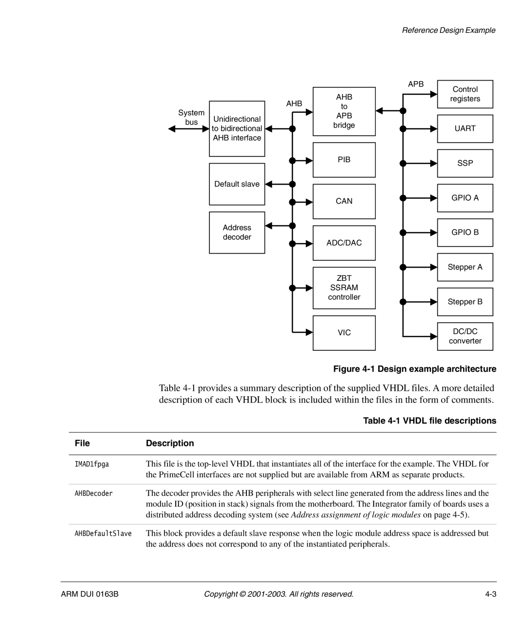
| Figure |
| Table |
| description of each VHDL block is included within the files in the form of comments. |
| Table |
|
|
File | Description |
|
|
IMAD1fpga | This file is the |
| the PrimeCell interfaces are not supplied but are available from ARM as separate products. |
|
|
AHBDecoder | The decoder provides the AHB peripherals with select line generated from the address lines and the |
| module ID (position in stack) signals from the motherboard. The Integrator family of boards uses a |
| distributed address decoding system (see Address assignment of logic modules on page |
|
|
AHBDefaultSlave | This block provides a default slave response when the logic module address space is addressed but |
| the address does not correspond to any of the instantiated peripherals. |
ARM DUI 0163B | Copyright © |