Reference Design Example
4.7.1Stepper x control register
The stepper controller control register defines the operating mode of the stepper.
Note
You must consider the maximum speed of the stepper motor when programming the step speed register or issuing consecutive single step commands in the stepper control register.
Ensure there is a delay, typically a few milliseconds, between a DOCOUNT and a SINGLESTEP. Failing to leave a delay between the end of the count and writing a SINGLESTEP command results in unpredictable behavior. The minimum duration of the delay depends on the stepper motor.
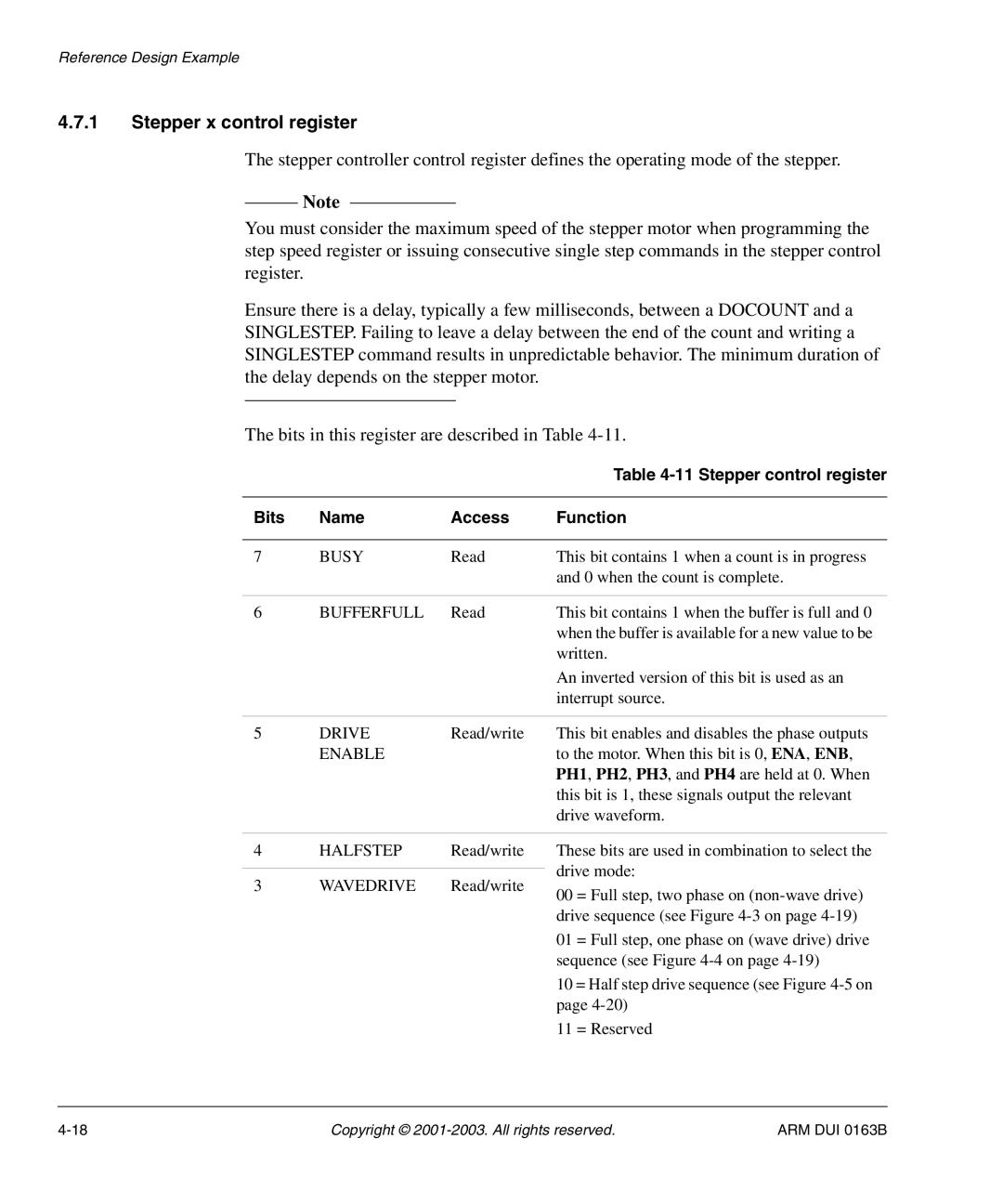
The bits in this register are described in Table
|
|
| Table |
|
|
|
|
Bits | Name | Access | Function |
|
|
|
|
7 | BUSY | Read | This bit contains 1 when a count is in progress |
|
|
| and 0 when the count is complete. |
|
|
|
|
6 | BUFFERFULL | Read | This bit contains 1 when the buffer is full and 0 |
|
|
| when the buffer is available for a new value to be |
|
|
| written. |
|
|
| An inverted version of this bit is used as an |
|
|
| interrupt source. |
|
|
|
|
5 | DRIVE | Read/write | This bit enables and disables the phase outputs |
| ENABLE |
| to the motor. When this bit is 0, ENA, ENB, |
|
|
| PH1, PH2, PH3, and PH4 are held at 0. When |
|
|
| this bit is 1, these signals output the relevant |
|
|
| drive waveform. |
4 | HALFSTEP | Read/write |
|
|
|
3 | WAVEDRIVE | Read/write |
These bits are used in combination to select the drive mode:
00 = Full step, two phase on
01 = Full step, one phase on (wave drive) drive sequence (see Figure
10 = Half step drive sequence (see Figure
11 = Reserved
Copyright © | ARM DUI 0163B |