Front Panel Redundancy
1.Use mouse button 1 to highlight a port, either AUI #1 or AUI #2.
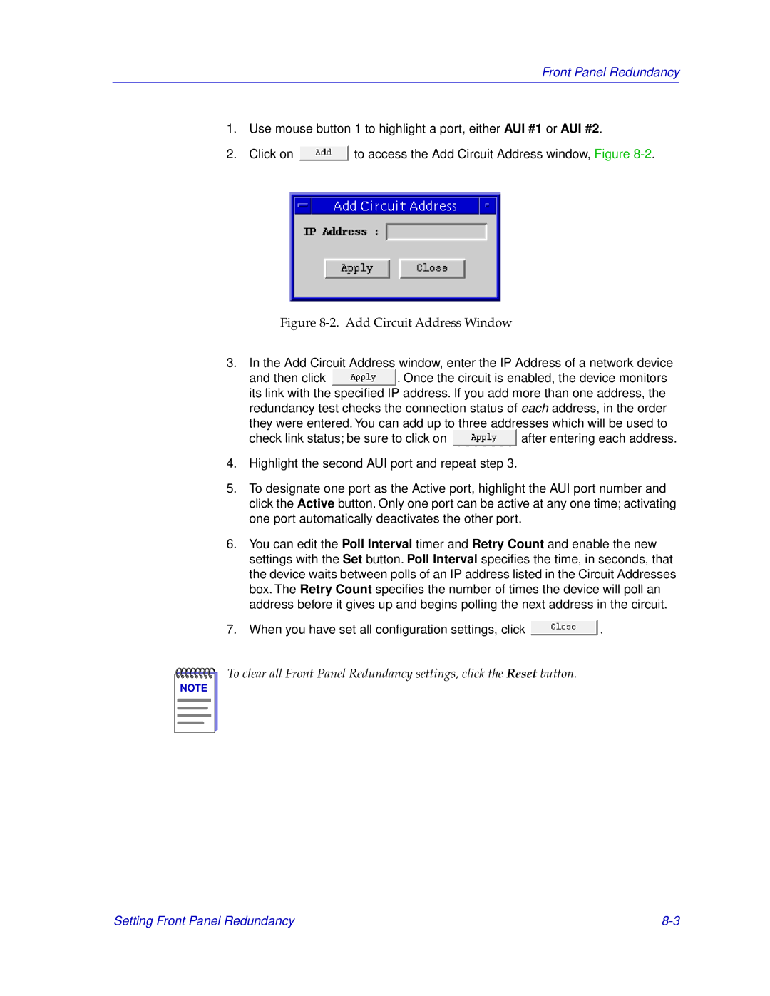
2.Click on ![]() to access the Add Circuit Address window, Figure
to access the Add Circuit Address window, Figure
Figure 8-2. Add Circuit Address Window
3.In the Add Circuit Address window, enter the IP Address of a network device
and then click ![]() . Once the circuit is enabled, the device monitors its link with the specified IP address. If you add more than one address, the redundancy test checks the connection status of each address, in the order
. Once the circuit is enabled, the device monitors its link with the specified IP address. If you add more than one address, the redundancy test checks the connection status of each address, in the order
they were entered. You can add up to three addresses which will be used to
check link status; be sure to click on ![]() after entering each address.
after entering each address.
4.Highlight the second AUI port and repeat step 3.
5.To designate one port as the Active port, highlight the AUI port number and click the Active button. Only one port can be active at any one time; activating one port automatically deactivates the other port.
6.You can edit the Poll Interval timer and Retry Count and enable the new settings with the Set button. Poll Interval specifies the time, in seconds, that the device waits between polls of an IP address listed in the Circuit Addresses box. The Retry Count specifies the number of times the device will poll an address before it gives up and begins polling the next address in the circuit.
7. When you have set all configuration settings, click | . |
NOTE |
To clear all Front Panel Redundancy settings, click the Reset button.
Setting Front Panel Redundancy |