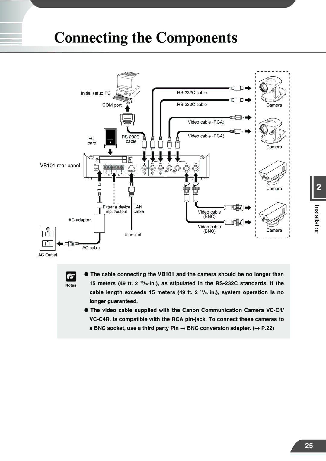
Connecting the Components
Initial setup PC
| COM port | |||
| PC |
|
| |
|
|
| cable | |
| card |
|
| |
|
|
|
| |
|
|
|
| |
VB101 rear panel |
|
|
| |
Dc In |
|
|
| |
| 1 | 2 | 1 | 2 |
|
| In |
| Out |
External device | LAN |
input/output | cable |
AC adapter |
|
Ethernet | |
AC cable |
|
AC Outlet
Video cable (RCA)
Video cable (RCA)
| RS232C |
|
| Video In |
|
|
| |
CC1 | CC2 | V1 | V2 |
| V3 |
| V4 |
|
|
|
|
|
|
|
|
|
|
|
|
|
|
|
|
|
|
|
|
|
|
|
|
|
|
|
|
|
|
|
|
|
|
|
|
|
|
|
|
|
|
|
|
|
|
|
|
|
|
|
|
|
|
|
Video cable
(BNC)
Video cable
(BNC)
Camera
Camera
Camera
Camera
2
Installation
c ● The cable connecting the VB101 and the camera should be no longer than | |
Notes | 15 meters (49 ft. 2 19/32 in.), as stipulated in the |
| |
| cable length exceeds 15 meters (49 ft. 2 19/32 in.), system operation is no |
| longer guaranteed. |
●The video cable supplied with the Canon Communication Camera
25