Connecting the Components
c
Notes
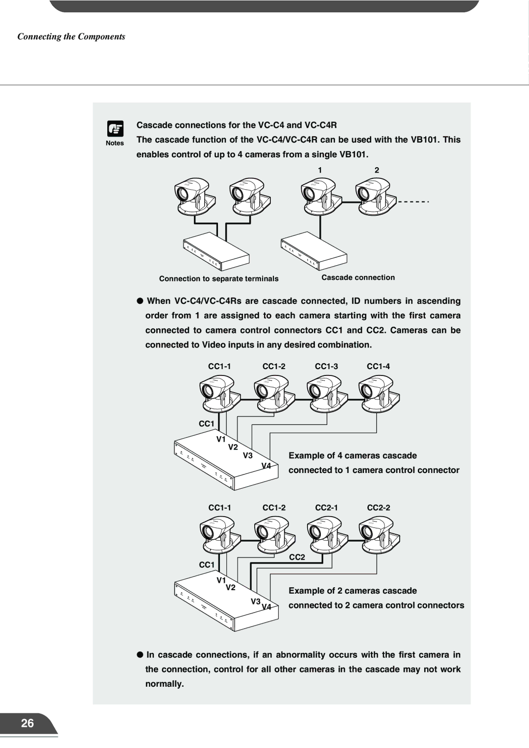
Cascade connections for the
The cascade function of the
12
Connection to separate terminals | Cascade connection |
●When
CC1
V1
V2
V3 | Example of 4 cameras cascade |
V4 | connected to 1 camera control connector |
|
CC1
V1
V2
| CC2 |
| Example of 2 cameras cascade |
V3 V4 | connected to 2 camera control connectors |
●In cascade connections, if an abnormality occurs with the first camera in the connection, control for all other cameras in the cascade may not work normally.
26