Text Part Number OL-14521-01
Americas Headquarters
Cisco Systems, Inc. All rights reserved
Iii
N T E N T S
Standard CTS-3000 Projector Setup
Overview A-1
Camera Target, 69-1674-xx, CTS-CAM-TOOL A-10
Vii
Viii
Conventions
Introduction
Related Documentation
This chapter is organized the same as Chapter
Chapter Organization
Routing Power and Signal Cables
Camera Target assembly used for camera focus and alignment
View of an Assembled Cisco TelePresence System
Assembly Overview
Conventions and Terminology
Uncrating and Unpacking
Tools and Equipment List
Overview Tools and Equipment List Cisco TelePresence System
Key Part Description Part Number Qty Ctn
Parts List
Display structure 700-23358-xx 35, 36
32, 33
Leveling feet
Codec Safety trays
Attach the Codec Safety trays to the Front Foot stabilizers
Rear and Front Foot stabilizers
Left and Right Display Shelf supports
Display Tilt brackets
Attach the Display Tilt brackets to each Display structure
Camera Assembly bracket
Upper and Lower Support crossbars
201108
Positioning the Display Structures
700-23598-xx 44 CTS3K-M Only. The Display shelves
This chapter for leveling purposes
Attaching bracketing hardware are
Described in , Building
Left, center, and right Plasma displays
Attach the Display shelves to the Display shelf supports
Attach the Display shelves to the Display shelf supports
Leveling Alignment Points
Purpose of Leveling the Plasma displays
Level the Display shelves along the X and Y axes
Leveling Goals
Cisco TelePresence System
Level the Plasma displays along the X and Y axes
Align the edges of Plasma displays
Cisco TelePresence System OL-14521-01
Apply the Black Buffer strips
Completing the Plasma display setup
Support struts 700-23752-xx
Lighting support brackets 700-23749-xx
End structure brackets 700-23750-xx
Plastic diffuser panel center 700-23745-xx
Reflector bottom end 700-23828-xx
Reflector bottom top side 700-23827-xx
Reflector bottom spacer 700-24152-xx
Reflector top center 700-23731-xx
Page
Support struts and Lighting Support brackets
Left and Right outer Support brackets from Figure
Four inner Support brackets from Figure
Four End structure brackets
Three Reflector bottom trays
Two Reflector bottom spacers
Left and Right vertical Reflector Bottom ends
Light Cup bracket
Three 5-foot Light fixtures
10 Left and Right 4-foot Side Light fixtures
11 Two center Metal Trim panels
Attach the two center Metal Trim panels
12 Two side Metal Trim panels
Attach the two side Metal Trim panels
13 Center Plastic Diffuser panel
Attach the center Plastic Diffuser panel
14 Left and Right Plastic Diffuser panels
Attach the left and right Plastic Diffuser panels
Four L-brackets
16 Two vertical Plastic Diffuser panels
17 Plastic Diffuser Panel brace
18 Center Reflector top
19 Left and Right Reflector tops
2017
21 Left and Right vertical Reflector ends
22 Left and Right corner Reflector Transition pieces
23 Two Metal Trim panels
Display shelf section left 700-23600-xx
Shelf, Product ID CTS3K-FUR-MAPLE
Display shelf section center 700-23599-xx
Display shelf section right 700-23598-xx
Shelf, Product ID CTS3K-M
Determining the Display Shelf Type
Accessory Cabinet
1shows the attachment hardware differences
Display Shelf Hardware
Attach the Display shelf hardware to the display shelves
Left Display shelf
Attach the left Display shelf
Center Display shelf
Attach the center Display shelf
Right Display shelf
Attach the right Display shelf
Accessory Cabinet
Building the Display Shelf Assembly, Product ID CTS3K-M
Attach the left Display shelf
Attach the center Display shelf
10 Right Display shelf
11 Accessory Cabinet
Building the Table Assembly
Miscellaneous Table Items
Number
Panel Assembly
Determining the Table Section Type
Building the Table Assembly, Product ID CTS3K-FUR-MAPLE
Four Molded foam bumpers and the four Table leg bases
Right-wing tabletop section
Right Table segment
Right-most Table Leg
Attach the right-most Table Leg
10 13
Right-center Table leg
Attach the Right-center Table leg
Left Table segment
Left center Table leg
Attach the left center Table leg
Left-most Table leg
Attach the left-most Table leg
Table Door
Attach the table door
Label and Safety Strap
Accessory cabinets
Building the Table Assembly, Product ID CTS3K-M
Four Molded foam bumpers and the four Table leg bases
22 23
Assemble the I/O modules for the inner molded foam bumpers
Right Wing Tabletop Section
Cisco TelePresence System
Right Most Table Leg
Attach the right most Table Leg
Center Table segment
Right center Table leg
Attach the right center Table leg
Left Table segment
204143
Left Most Table Leg
Attach the left most Table leg
Microphone Assembly
Left Connecting Tabletop Section
Accessory cabinets
Assembling the Remaining Cisco TelePresence Elements
Microphone Assembly
Assembly
Power I/O Connections
Projector Assembly
Audio/Video Extension Unit
Projector Screen Assembly, Type
Cisco IP Phone
Auxiliary Control Unit
Bracket
Target Assembly
Camera Assembly
201165
I/O Modules for Outer Foam Bumpers
I/O Modules Inner Foam Bumpers
Attach the Projector to the Projector mounting bracket
Projector Assembly
201169
VGA Module
Rotated for clarity
Attach the center Privacy panel
Attach the left Privacy panel
Attach the right Privacy panel
10 Privacy Panel Assembly
Attach the right-wing Privacy panel
11 Privacy Panel Assembly
Attach the Cable management bars to the three Codecs
Codec Assembly
Attach the Codec attachment brackets to the three Codecs
201177
15 Audio/Video Expansion Unit and Bracket
16 Audio/Video Extension Unit
17 Speaker Assembly
18 Speaker Assembly
Attach the Speakers to the Speaker boards
19 Speaker Assembly
20 Projector Screen Assembly
21 Auxiliary Control Unit
22 Camera Target Assembly
Specific part numbers
Routing Power and Signal Cables
Routing Power and Signal Cables Parts List
Dual PDU installation to left accessory cabinet
Right-side PDU installation to right accessory cabinet
Attach the center PDU to the center privacy panel
Table assembly PDU attachment to the center Privacy panel
Routing Power Cables for I/O Modules and Projector
Routing Signal cables from the Table assembly
Route the signal cables from the table assembly
IP Phone Signal VGA Peripheral
Cisco TelePresence System OL-14521-01
14Microphones
205760
Cabling the Speakers
Auxiliary Control Unit
11 Cabling the Plasma displays
Connect the plasma display cables
Hdmi connector
Connect the camera assembly cables
13 Cabling the Codec Signal Cables
Connect the codec signal cables
14 Routing the Codec Power Cables
Connect the codec power cables
Auxiliary Control Unit Projector
Presentation Codec
OL-14521-01
Hood Assembly Figure
Loading CTS Administration Software
Bootup Completed
System IP Address
Setting Up CTS Components
Configuring an Alternate Tftp Server Optional
Selecting the Light Level
Setting Up the Displays
Only
Troubleshooting Displays
Problem Possible Cause Action
Start the Software Setup
Setting Up the Cameras
Auto Adjust
Attach the Camera Target
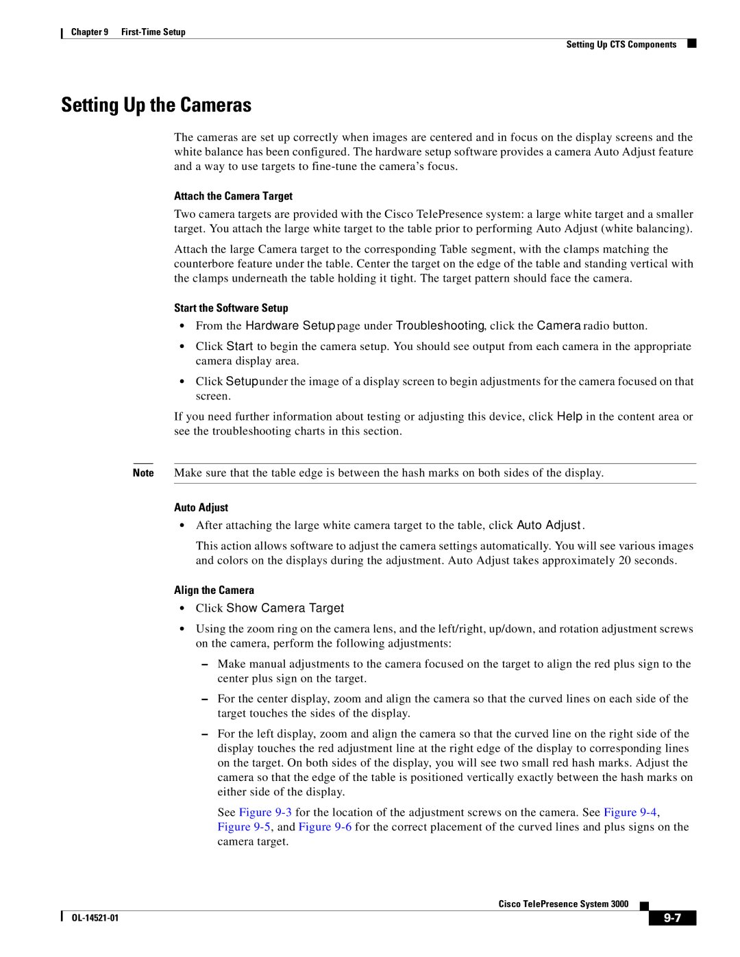
Left/right screws Rotation screws Lens Up/down screw
Screen border
Show All Camera Targets
Attaching the Camera Hood Assembly
Flipping the Video Image
Focus the Camera
Attaching the Camera Hood Assembly
Use -2to troubleshoot problems with cameras
Troubleshooting Cameras
Setting Up the Microphones
Setting Up the Speakers
Troubleshooting Speakers
Use -3to troubleshoot problems with speakers
Use -4to troubleshoot problems with microphones
Troubleshooting Microphones
Standard CTS-3000 Projector Setup
Setting Up the Projector
Use the Up Arrow and Down Arrow keys and highlight Setting
Press the Menu key on the remote control
Press the Right Arrow key and select on
Press the Up Arrow and Down Arrow keys and select Ceiling
First-Time Setup Setting Up CTS Components
Click Presentation Devices on the Hardware Setup window
Projector Setup With an Auxiliary Control Unit
Click Presentation Devices on the Hardware Setup window
Use -5to troubleshoot problems with presentation devices
Troubleshooting Presentation Devices
Other Devices
Cleaning the Camera lens
Cleaning the Plasma displays
Maintaining the Tabletop
10-1
10-2
Maintaining the Projector
11-1
Replacing the Camera Cluster-Part Number
Required Information, Tools, and Equipment
11-2
Powering Off the System
Removing the Camera Cluster
11-3
Replacing a Plasma Display-Part Number CTS-DISP-65-GEN2
11-4
Removing Audio Components
11-5
Removing the Left Tabletop Door Section
Removing a Display Shelf
11-6
Removing the Display Screen and Completing the Procedure
11-7
11-8
Replacing a Speaker-Part Number CTS-LDSPKR
Removing and Replacing a Speaker
11-9
11-10
Removing and Replacing a Codec
11-11
Remove the L brackets from the codec
11-12
Replacing a Microphone-Part Number CTS-MIC
Removing and Replacing a Microphone
11-13
Replacing a Light Fixture-Part Number CTS-LIGHT-FIXT
Replacement Bulbs
Replacing a Light Fixture
11-14
11-15
See , Building the Lighting Assembly for more information
11-16
11-17
Replacing the Projector Lamp-Part Number
11-18
11-19
Replacing the Projector-Part Number CTS-PRJTR-GEN1
11-20
Replacing a PDU-Part Number CTS-PWR-PDU
11-21
Replacing the Auxiliary Control Unit-Part Number
Replacing a Display Shelf
11-22
Removing and Replacing a Display Shelf Row Table Section
11-23
Replacing a Table Top Section
Complete these steps to replace a table top section
11-24
Removing and Replacing a Table Top Section
11-25
11-26
Number Part Number Part Description Qty Reference
Sub-Kit ID Chapter Parts List
Overview
OL-14521-01
Carton 4 of 47 Secondary Codec, 800-28202-xx, CTS-CODEC-SEC
With mounting accessories
Carton 3 of 47 Primary Codec, 800-28191-xx, CTS-CODEC-PRIM
Carton 6 of 47 Projector, 74-4824-xx, CTS-PRJTR-GEN1
Carton 5 of 47 Secondary Codec, 800-28202-xx, CTS-CODEC-SEC
Carton 7 of 47 Speaker, 74-4740-xx, CTS-LDSPKR
Carton 8 of 47 Speaker, 74-4740-xx, CTS-LDSPKR
Xxxx-xx Power cord Chapter Refer to Appendix
Carton 10 of 47 Power Cord, 37-08xx-xx, PWR-CORD10-xx
Carton 11 of 47 Camera Bracket, 69-1627-xx, CTS3K-STRUCTURE
Carton 12 of 47 Brackets, 69-1632-xx, CTS3K-STRUCTURE
69-1624-xx 700-23359-xx Front foot stabilizer Chapter
74-4605-xx Inch high-definition display Chapter
Carton 20 of 47 Plasma Display, 74-4881-xx, CTS-DISP-65-GEN2
Carton 25 of 47 Foam Bumpers, 69-1634-xx, CTS3K-STRUCTURE
Carton 28 of 47 Light Fixture, 74-5361-xx, CTS-LIGHT-FIXT
Carton 27 of 47 Light Fixture, 74-5361-xx, CTS-LIGHT-FIXT
Carton 29 of 47 Light Fixture, 74-5361-xx, CTS-LIGHT-FIXT
Carton 30 of 47 Light Fixture, 74-5362-xx, CTS-LIGHT-FIXT
Carton 34 of 47 Privacy Panels, 69-1629-xx, CTS3K-STRUCTURE
Carton 31 of 47 Light Fixture, 74-5362-xx, CTS-LIGHT-FIXT
Carton 32 of 47 Camera Target, 69-1674-xx, CTS-CAM-TOOL
Carton 40 of 47 Display Shelves and Codec Tray
Carton 39 of 47 Projector Screen, 74-5416-xx, CTS3K-SCREEN
Carton 44 of 47 Tabletop, 69-1638-xx, CTS3K-FUR-MAPLE
Carton 47 of 47 Speaker Boards, 69-1641-xx, CTS3K-FUR-MAPLE
Carton 45 of 47 Tabletop, 69-1639-xx, CTS3K-FUR-MAPLE
Carton 46 of 47 Display Shelf, 69-1640-xx, CTS3K-FUR-MAPLE
OL-14521-01
Carton 4 of 44 Secondary Codec, 800-28202-xx, CTS-CODEC-SEC
Carton 3 of 44 Primary Codec, 800-28191-xx, CTS-CODEC-PRIM
CP-7975G 68-3309-01 Cisco IP Phone 7975G Chapter
Spline Draw bolt
Carton 6 of 44 Projector, 74-4824-xx, CTS-PRJTR-GEN1
Carton 5 of 44 Secondary Codec, 800-28202-xx, CTS-CODEC-SEC
Carton 7 of 44 Speaker, 74-4740-xx, CTS-LDSPKR
Carton 8 of 44 Speaker, 74-4740-xx, CTS-LDSPKR
Xxxx-xx Power cord Chapter
Carton 10 of 44 Power Cord, 37-08xx-xx, PWR-CORD10-xx
Carton 9 of 44 Speaker, 74-4740-xx, CTS-LDSPKR
Carton 12 of 44 Brackets, 69-1632-xx, CTS3K-STRUCTURE
69-1628-xx 700-23362-xx Privacy panel right-wing Chapter
Carton 20 of 44 Plasma Display, 74-4881-xx, CTS-DISP-65-GEN2
Carton 24 of 44 Light Fixture, 74-5361-xx, CTS-LIGHT-FIXT
Carton 26 of 44 Light Fixture, 74-5361-xx, CTS-LIGHT-FIXT
Carton 25 of 44 Light Fixture, 74-5361-xx, CTS-LIGHT-FIXT
Carton 27 of 44 Light Fixture, 74-5362-xx, CTS-LIGHT-FIXT
Carton 28 of 44 Light Fixture, 74-5362-xx, CTS-LIGHT-FIXT
Carton 31 of 44 Privacy Panels, 69-1629-xx, CTS3K-STRUCTURE
69-1626-xx 700-23339-xx Display shelf support left Chapter
Carton 36 of 44 Projector Screen, 74-5416-xx, CTS3K-SCREEN
Carton 43 of 44 Foam Bumpers, 69-1634-xx, CTS3K-STRUCTURE
Appendix a Appendix a Parts List Sorted by Carton
OL-14521-01
Part Description Part Number Qty
Asia Pacific
Argentina
India, UAE, South Africa
Australia
China
Italy
Israel
Japan
North America
Switzerland
37-0843-01 Modules power/Ethernet
United Kingdom
74-4862-01