xvi
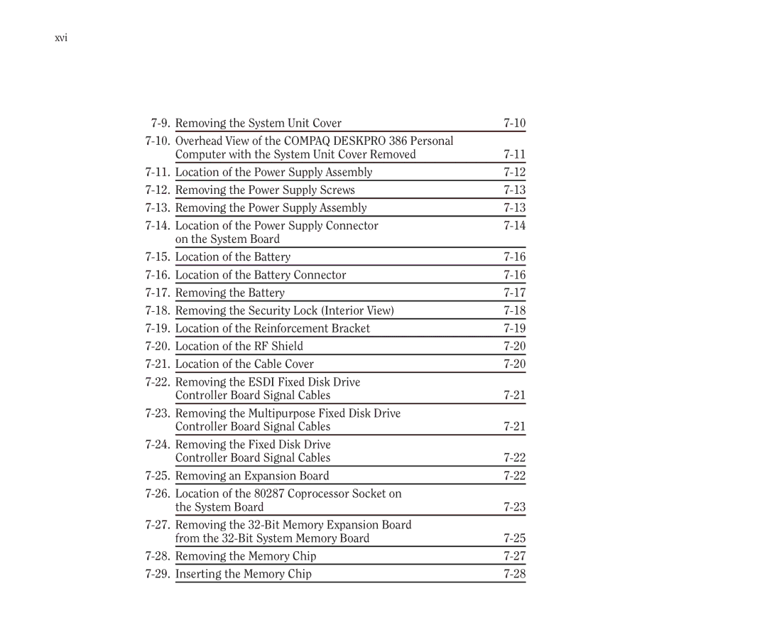
Removing the System Unit Cover | ||
Overhead View of the COMPAQ DESKPRO 386 Personal |
| |
| Computer with the System Unit Cover Removed | |
Location of the Power Supply Assembly | ||
Removing the Power Supply Screws | ||
Removing the Power Supply Assembly | ||
Location of the Power Supply Connector | ||
| on the System Board |
|
Location of the Battery | ||
Location of the Battery Connector | ||
Removing the Battery | ||
Removing the Security Lock (Interior View) | ||
Location of the Reinforcement Bracket | ||
Location of the RF Shield | ||
Location of the Cable Cover | ||
Removing the ESDI Fixed Disk Drive |
| |
| Controller Board Signal Cables | |
Removing the Multipurpose Fixed Disk Drive |
| |
| Controller Board Signal Cables | |
Removing the Fixed Disk Drive |
| |
| Controller Board Signal Cables | |
Removing an Expansion Board | ||
Location of the 80287 Coprocessor Socket on |
| |
| the System Board | |
Removing the |
| |
| from the | |
Removing the Memory Chip | ||
Inserting the Memory Chip |
