. . . . . . . . . . . . . . . . . . . . . . . . .
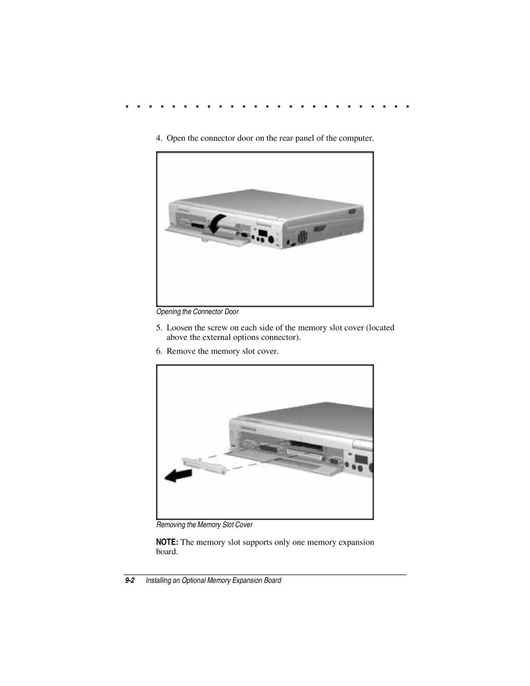
4. Open the connector door on the rear panel of the computer.
Opening the Connector Door
5.Loosen the screw on each side of the memory slot cover (located above the external options connector).
6.Remove the memory slot cover.
Removing the Memory Slot Cover
NOTE: The memory slot supports only one memory expansion board.
