Chapter 2 -
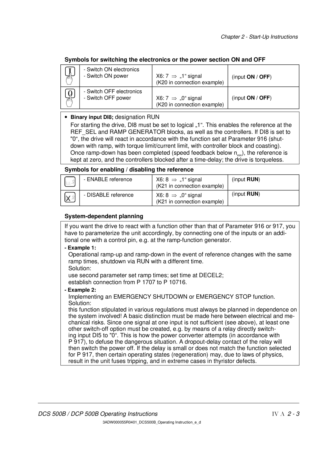
Symbols for switching the electronics or the power section ON and OFF
| - Switch ON electronics |
|
|
| - Switch ON power | X6: 7 ⇒ „1“ signal | (input ON / OFF) |
|
| (K20 in connection example) |
|
|
|
|
|
| - Switch OFF electronics |
|
|
| - Switch OFF power | X6: 7 ⇒ „0“ signal | (input ON / OFF) |
|
| (K20 in connection example) |
|
|
|
|
|
•Binary input DI8; designation RUN
For starting the drive, DI8 must be set to logical „1“. This enables the reference at the REF_SEL and RAMP GENERATOR blocks, as well as the controllers. If DI8 is set to "0“, the drive will react in accordance with the function set at Parameter 916 (shut- down with ramp, with torque limit/current limit, with controller block and coasting).
Once
Symbols for enabling / disabling the reference
|
|
|
| - ENABLE reference | X6: 8 | ⇒ „1“ signal | (input RUN) |
|
|
|
| ||||
|
|
|
|
| (K21 in connection example) |
| |
|
|
|
|
|
|
|
|
|
|
|
| - DISABLE reference | X6: 8 | ⇒ „0“ signal | (input RUN) |
|
|
|
| ||||
|
|
|
|
| (K21 in connection example) |
| |
|
|
|
|
|
|
|
|
System-dependent planning
If you want the drive to react with a function other than that of Parameter 916 or 917, you have to parameterize the unit accordingly, by connecting one of the inputs or an addi- tional one with a control pin, e.g. at the
- Example 1:
Operational
Solution:
use second parameter set ramp times; set time at DECEL2; establish connection from P 1707 to P 10716.
- Example 2:
Implementing an EMERGENCY SHUTDOWN or EMERGENCY STOP function. Solution:
this function stipulated in various regulations must always be planned in dependence on the system involved! A basic distinction must be made here between electrical and me- chanical risks. Since one signal at one input is not sufficient (see above), at least one other
ing input DI5 to "0“. This is how the power converter attempts (in accordance with P 917), to defuse the dangerous situation. A
DCS 500B / DCP 500B Operating Instructions | IV A 2 - 3 |
3ADW000055R0401_DCS500B_Operating Instruction_e_d
