DCS 500B / DCP 500B Operating |
230V 50Hz
L1 MP
1 | 1 | 1 |
F7 | F5 | F8 |
2 | 2 | 2 |
400V 50Hz
L1 L2 L3
F1
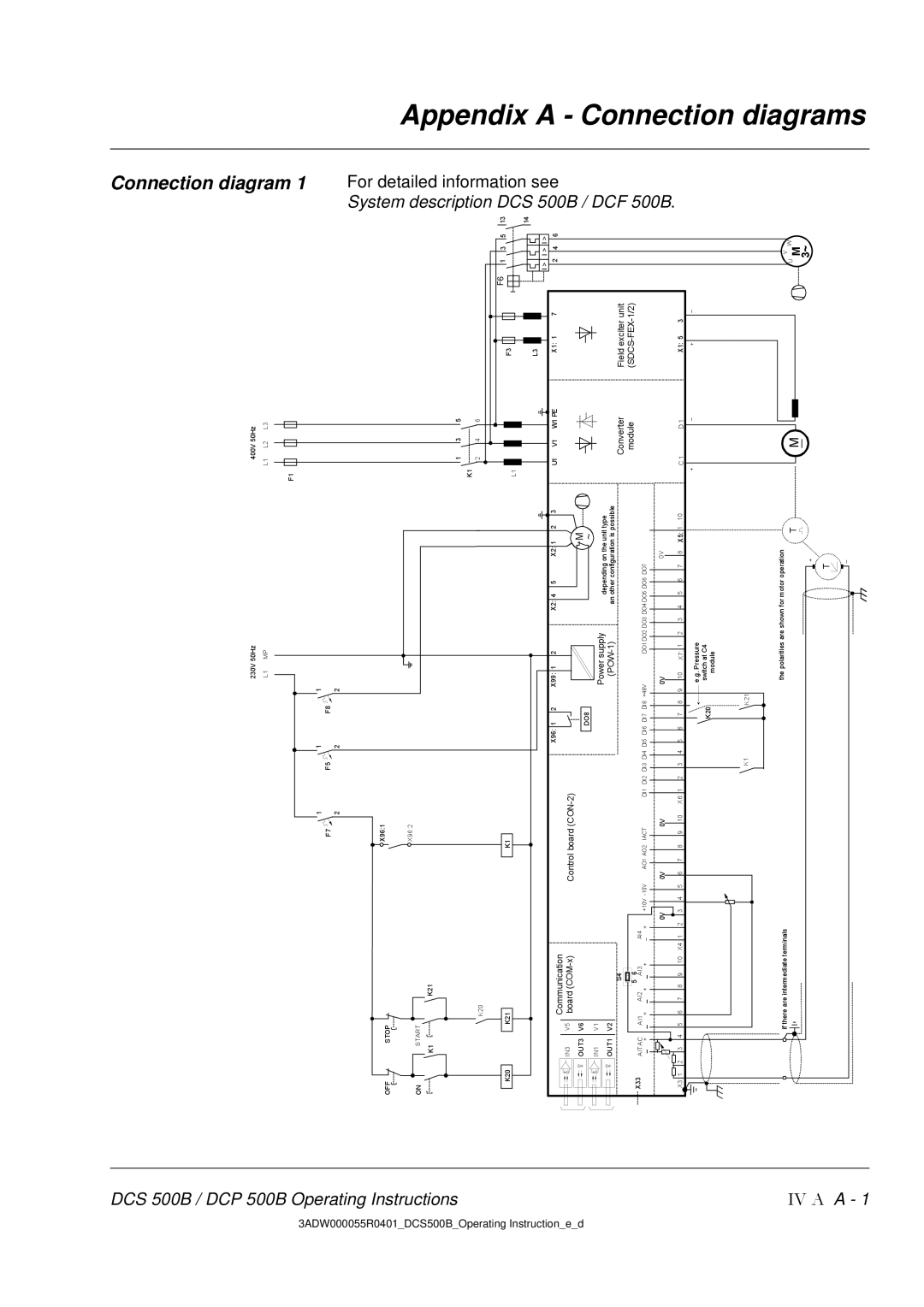
Connection diagram 1
3ADW000055R0401 DCS500B | Instructions |
Operating |
|
OFF | STOP | X96:1 |
|
![]() X96:2
X96:2
ONSTART
K1 ![]()
![]()
![]()
![]()
![]()
![]()
![]() K21
K21
K20
1 | 3 | 5 |
K1 |
|
|
2 | 4 | 6 |
System description
For detailed information
Appendix
Instruction e d |
IV A
K20K21
| IN3 |
| V5 | Communication |
|
|
| ||||
|
| board |
|
|
| ||||||
| OUT3 | V6 |
|
|
|
|
|
|
|
| |
| IN1 |
| V1 |
|
|
|
|
|
|
|
|
| OUT1 | V2 |
|
|
|
|
|
|
|
| |
|
|
|
|
|
| S4 |
|
|
|
| |
X33 | AITAC | AI1 |
| AI2 | 5 | 6 |
| AI4 |
|
| |
+ | + | AI3 | + | +10V | |||||||
| _ | + | _ | _ | _ | + | _ | ||||
|
|
|
|
|
|
|
|
|
|
| 0V |
X3: 1 | 2 3 | 4 | 5 | 6 | 7 | 8 | 9 | 10 | X4: 1 | 2 | 3 4 5 |
if there are intermediate terminals
| K1 |
|
|
|
|
|
|
|
|
|
| |
|
|
|
| X96: 1 | 2 |
| X99: 1 | 2 | X2: 4 | 5 | X2: 1 2 3 | |
Control board |
|
|
|
|
|
|
| M | ||||
|
|
|
|
|
|
|
|
|
|
|
| |
|
|
|
| DO8 |
|
|
| Power supply |
|
| ~ | |
|
|
|
|
|
|
|
| depending on the unit type | ||||
|
|
|
|
|
|
|
|
| an other configuration is possible | |||
AO1 AO2 | IACT | DI1 DI2 DI3 DI4 DI5 DI6 DI7 | DI8 | +48V | DO1 DO2 DO3 DO4 DO5 DO6 DO7 |
| ||||||
0V |
|
| 0V |
|
|
| 0V |
|
|
| 0V | |
6 7 8 | 9 | 10 X6: 1 2 3 4 5 6 7 | 8 | 9 10 | X7: 1 2 | 3 4 5 | 6 7 | 8 X5: 1...10 | ||||
|
|
|
|
|
|
|
| e.g. Pressure |
|
|
| |
K20 | switch at C4 | |
module | ||
|
K1K21
the polarities are shown for motor operation
T
+
L1 |
U1 V1 W1 PE
Converter module
C 1 | D 1 |
+_
M
F3
L3
X1: 1 | 7 |
Field exciter unit
X1: 5 | 3 |
+ | _ |
|
F6 1 3 5
![]()
![]()
![]()
![]()
![]() I > I > I > 2 4 6
I > I > I > 2 4 6
V
U MW
3~
13 DCS
14 500B/
DCF 500B .
see
A - Connection diagrams
A - 1
T
![]()
![]() _
_