Chapter 3 - Handling of Control Panel CDP 31x
Parameter Mode The Parameter Mode is used for:
-change the structure in the firmware
-show signals and their actual status
PAR | - show and change values of parameters, if they are not | |||
|
| |||
| When the Parameter mode is entered parameter 101 appears after | |||
| initialization, otherwise the selected parameter is shown. | |||
|
|
|
| |
|
|
|
|
|
|
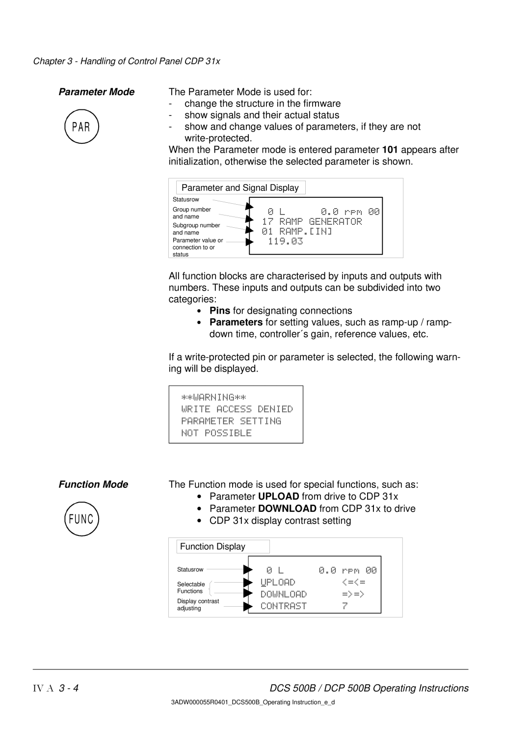
| Parameter and Signal Display |
|
|
|
|
|
|
|
Statusrow
Group number and name
Subgroup number and name Parameter value or connection to or status
0 L 0.0 rpm 00
17 RAMP GENERATOR
01RAMP.[IN]
119.03
All function blocks are characterised by inputs and outputs with numbers. These inputs and outputs can be subdivided into two categories:
•Pins for designating connections
•Parameters for setting values, such as
If a
**WARNING**
WRITE ACCESS DENIED PARAMETER SETTING NOT POSSIBLE
Function Mode | The Function mode is used for special functions, such as: | |||||
| • Parameter UPLOAD from drive to CDP 31x | |||||
FUNC | • Parameter DOWNLOAD from CDP 31x to drive | |||||
• | CDP 31x display contrast setting | |||||
| Function Display |
|
|
| ||
| Statusrow |
|
|
| 0 L | 0.0 rpm 00 |
|
|
| ||||
| Selectable |
|
|
| UPLOAD | <=<= |
|
|
|
| |||
| Functions |
|
|
| DOWNLOAD | =>=> |
| Display contrast |
| ||||
|
| CONTRAST | 7 | |||
| adjusting |
|
|
| ||
IV A 3 - 4 | DCS 500B / DCP 500B Operating Instructions |
3ADW000055R0401_DCS500B_Operating Instruction_e_d