Chapter 4 - Signals and Troubleshooting
4.6 Status Signals
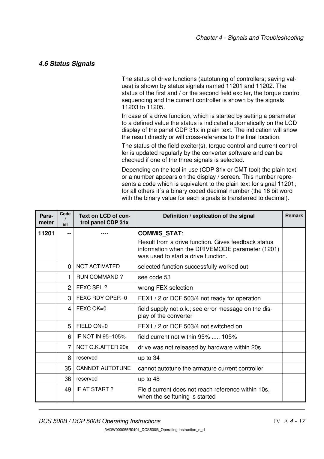
The status of drive functions (autotuning of controllers; saving val- ues) is shown by status signals named 11201 and 11202. The status of the first and / or the second field exciter, the torque control sequencing and the current controller is shown by the signals 11203 to 11205.
In case of a drive function, which is started by setting a parameter to a defined value the status is indicated automatically on the LCD display of the panel CDP 31x in plain text. The indication will show the result directly or will
The status of the field exciter(s), torque control and current control- ler is updated regularly by the converter software and can be checked if one of the three signals is selected.
Depending on the tool in use (CDP 31x or CMT tool) the plain text or a number appears on the display / screen. This number repre- sents a code which is equivalent to the plain text for signal 11201; for all others it´s a binary coded decimal number (the 16 bit word with the binary value for each signals is transferred to decimal).
| Para- |
|
| Code |
|
| Text on LCD of con- |
|
| Definition / explication of the signal |
|
| Remark |
|
|
|
| / |
|
|
|
|
|
|
| ||||
| meter |
|
|
|
| trol panel CDP 31x |
|
|
|
|
|
|
| |
|
|
| bit |
|
|
|
|
|
|
|
|
| ||
|
|
|
|
|
|
|
|
|
|
|
|
|
| |
11201 |
|
| COMMIS_STAT: |
|
|
|
| |||||||
|
|
|
|
|
|
|
|
|
| Result from a drive function. Gives feedback status |
|
|
|
|
|
|
|
|
|
|
|
|
|
| information when the DRIVEMODE parameter (1201) |
| |||
|
|
|
|
|
|
|
|
|
| was used to start a drive function. |
|
|
|
|
|
|
|
|
|
|
|
|
|
|
|
|
| ||
|
|
| 0 |
| NOT ACTIVATED |
|
| selected function successfully worked out |
|
|
|
| ||
|
|
|
|
|
|
|
|
|
|
|
|
| ||
|
|
| 1 |
| RUN COMMAND ? |
|
| see code 53 |
|
|
|
| ||
|
|
|
|
|
|
|
|
|
|
|
|
| ||
|
|
| 2 |
| FEXC SEL ? |
|
| wrong FEX selection |
|
|
|
| ||
|
|
|
|
|
|
|
|
|
|
|
|
| ||
|
|
| 3 |
| FEXC RDY OPER=0 |
|
| FEX1 / 2 or DCF 503/4 not ready for operation |
|
|
|
| ||
|
|
|
|
|
|
|
|
|
|
|
|
| ||
|
|
| 4 |
| FEXC OK=0 |
|
| field supply not o.k.; see error message on the dis- |
|
|
|
| ||
|
|
|
|
|
|
|
|
|
| play of the converter |
|
|
|
|
|
|
|
|
|
|
|
|
|
|
|
|
| ||
|
|
| 5 |
| FIELD ON=0 |
|
| FEX1 / 2 or DCF 503/4 not switched on |
|
|
|
| ||
|
|
|
|
|
|
|
|
|
|
|
|
| ||
|
|
| 6 |
| IF NOT IN |
|
| field current not within 95% ..... 105% |
|
|
|
| ||
|
|
|
|
|
|
|
|
|
|
|
|
| ||
|
|
| 7 |
| NOT O.K.AFTER 20s |
|
| drive was not released by hardware within 20s |
|
|
|
| ||
|
|
|
|
|
|
|
|
|
|
|
|
| ||
|
|
| 8 |
| reserved |
|
| up to 34 |
|
|
|
| ||
|
|
|
|
|
|
|
|
|
|
|
|
| ||
|
|
| 35 |
| CANNOT AUTOTUNE |
|
| cannot autotune the armature current controller |
|
|
|
| ||
|
|
|
|
|
|
|
|
|
|
|
|
| ||
|
|
| 36 |
| reserved |
|
| up to 48 |
|
|
|
| ||
|
|
|
|
|
|
|
|
|
|
|
|
| ||
|
|
| 49 |
| IF AT START ? |
|
| Field current does not reach reference within 10s, |
|
|
|
| ||
|
|
|
|
|
|
|
|
|
| when the selftuning is started |
|
|
|
|
|
|
|
|
|
|
|
|
|
|
|
|
|
| |
|
|
|
|
|
|
|
|
|
|
|
|
|
|
|
| DCS 500B / DCP 500B Operating Instructions | IV A 4 - 17 | ||||||||||||
3ADW000055R0401_DCS500B_Operating Instruction_e_d