Chapter 4 - Signals and Troubleshooting
| Code |
|
| Text on |
|
| Definition / |
|
| Signal |
| Remark | |
| seven |
|
| LCD of control panel |
|
| Possible source |
|
| number |
|
| |
| segm. |
|
| ||||||||||
|
|
| CDP 31x |
|
|
|
|
| (ALARM_WORD_1/2) |
|
| ||
| display |
|
|
|
|
|
|
|
|
| |||
|
|
|
|
|
|
|
|
|
|
|
|
| |
|
|
|
|
|
|
|
|
|
|
|
| ||
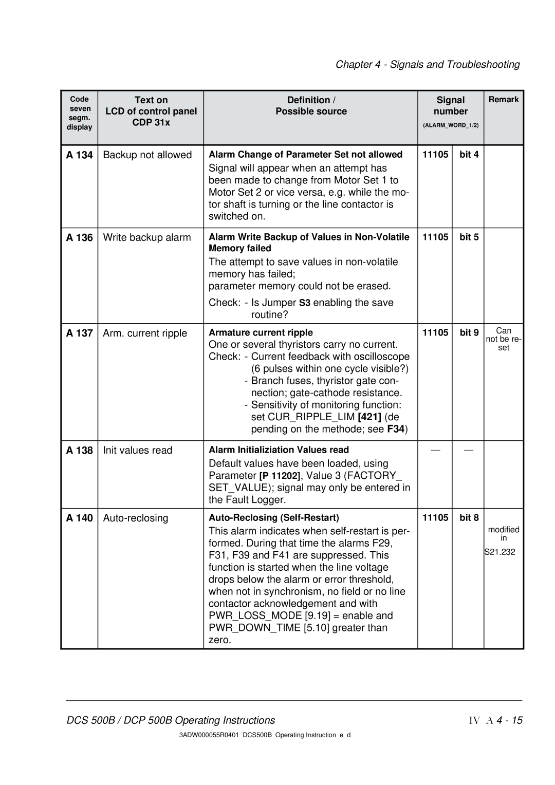
A 134 | Backup not allowed |
|
| Alarm Change of Parameter Set not allowed |
| 11105 | bit 4 |
| |||||
|
|
|
|
|
|
| Signal will appear when an attempt has |
|
|
|
|
|
|
|
|
|
|
|
|
| been made to change from Motor Set 1 to |
|
|
|
|
|
|
|
|
|
|
|
|
| Motor Set 2 or vice versa, e.g. while the mo- |
|
|
|
|
|
|
|
|
|
|
|
|
| tor shaft is turning or the line contactor is |
|
|
|
|
|
|
|
|
|
|
|
|
| switched on. |
|
|
|
|
|
|
|
|
|
|
|
|
|
|
| |||||
A 136 | Write backup alarm |
|
| Alarm Write Backup of Values in |
| 11105 | bit 5 |
| |||||
|
|
|
|
|
|
| Memory failed |
|
|
|
|
|
|
|
|
|
|
|
|
| The attempt to save values in |
|
|
|
|
|
|
|
|
|
|
|
|
| memory has failed; |
|
|
|
|
|
|
|
|
|
|
|
|
| parameter memory could not be erased. |
|
|
|
|
|
|
|
|
|
|
|
|
| Check: - Is Jumper S3 enabling the save |
|
|
|
|
|
|
|
|
|
|
|
|
| routine? |
|
|
|
|
|
|
|
|
|
|
|
|
|
| ||||||
A 137 | Arm. current ripple |
| Armature current ripple |
| 11105 | bit 9 | Can | ||||||
|
|
|
|
|
| One or several thyristors carry no current. |
|
|
|
|
| not be re- | |
|
|
|
|
|
|
|
|
|
|
| set | ||
|
|
|
|
|
| Check: - Current feedback with oscilloscope |
|
|
|
|
|
| |
|
|
|
|
|
|
| (6 pulses within one cycle visible?) |
|
|
|
|
|
|
|
|
|
|
|
|
| - Branch fuses, thyristor gate con- |
|
|
|
|
|
|
|
|
|
|
|
|
| nection; |
|
|
|
|
|
|
|
|
|
|
|
|
| - Sensitivity of monitoring function: |
|
|
|
|
|
|
|
|
|
|
|
|
| set CUR_RIPPLE_LIM [421] (de |
|
|
|
|
|
|
|
|
|
|
|
|
| pending on the methode; see F34) |
|
|
|
|
|
|
|
|
|
|
|
|
|
|
|
| ||||
A 138 | Init values read |
|
| Alarm Initializiation Values read |
|
| | |
| ||||
|
|
|
|
|
|
| Default values have been loaded, using |
|
|
|
|
|
|
|
|
|
|
|
|
| Parameter [P 11202], Value 3 (FACTORY_ |
|
|
|
|
|
|
|
|
|
|
|
|
| SET_VALUE); signal may only be entered in |
|
|
|
|
|
|
|
|
|
|
|
|
| the Fault Logger. |
|
|
|
|
|
|
|
|
|
|
|
|
|
|
|
| ||||
A 140 |
|
|
|
| 11105 | bit 8 |
| ||||||
|
|
|
|
|
|
| This alarm indicates when |
|
|
|
|
| modified |
|
|
|
|
|
|
| formed. During that time the alarms F29, |
|
|
|
|
| in |
|
|
|
|
|
|
|
|
|
|
|
| S21.232 | |
|
|
|
|
|
|
| F31, F39 and F41 are suppressed. This |
|
|
|
|
| |
|
|
|
|
|
|
| function is started when the line voltage |
|
|
|
|
|
|
|
|
|
|
|
|
| drops below the alarm or error threshold, |
|
|
|
|
|
|
|
|
|
|
|
|
| when not in synchronism, no field or no line |
|
|
|
|
|
|
|
|
|
|
|
|
| contactor acknowledgement and with |
|
|
|
|
|
|
|
|
|
|
|
|
| PWR_LOSS_MODE [9.19] = enable and |
|
|
|
|
|
|
|
|
|
|
|
|
| PWR_DOWN_TIME [5.10] greater than |
|
|
|
|
|
|
|
|
|
|
|
|
| zero. |
|
|
|
|
|
|
|
|
|
|
|
|
|
|
|
|
|
|
|
|
DCS 500B / DCP 500B Operating Instructions | IV A 4 - 15 |
3ADW000055R0401_DCS500B_Operating Instruction_e_d