Chapter 4 - Signals and Troubleshooting
4.4 Fault Signals (F)
The fault signals will be shown on the seven segment display of the control board
All fault signals - with the exception of F 17, F 18 and F 44 - can be reset (after elimination of the faults); F 20 would be self resetting, if the communication had been
For resetting (RESET) of fault signals the following steps are re- quired:
•Switching off the commands ON/OFF and RUN
•Elimination of the faults
•Fault acknowledgement, i.e. resetting (RESET)
a)as described for CDP 31x
or | b) by |
| to high (logical one) via a binary input |
| (default setting = DI6). |
•Depending on the application conditions generate the commands ON/OFF and RUN once more.
The fault signals will result in switching off the signal [10910] resp. in stopping the drive
If a fault occurs, there will be three different possibilities of reaction (see column “Remark” in the fault list):
(1)Fault will switch off the signals energizing the main contactor, the field contactor and the fan contactor.
(2)Fault will switch off the signals energizing the main contactor and the field contactor.
(3)Fault will switch off at least the signal energizing the main contactor.
| Code |
|
| Text on |
| Definition / |
| Status |
| Remark | |
| seven |
|
| LCD of control panel |
| Action |
| signal |
|
| |
| segm. |
| |||||||||
|
|
| CDP 31x |
|
|
| (FAULT_WORD_1/2) |
|
| ||
| display |
|
|
|
|
|
|
| |||
|
|
|
|
|
|
|
|
|
|
| |
|
|
|
|
|
|
|
|
|
|
|
|
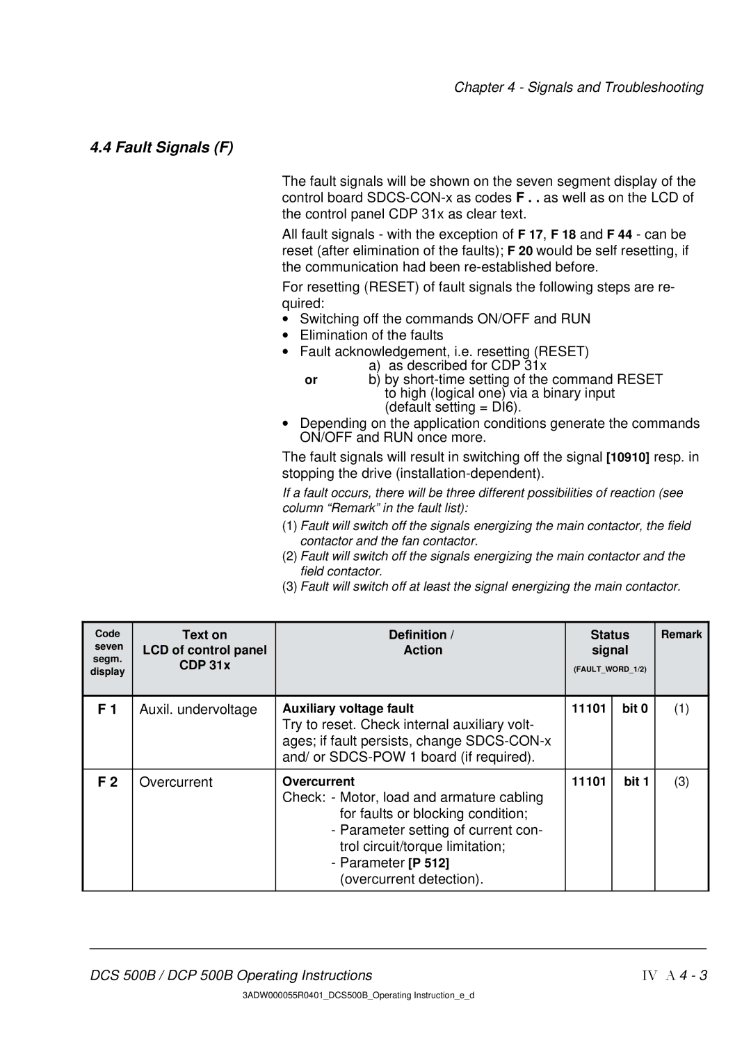
| F 1 |
| Auxil. undervoltage |
| Auxiliary voltage fault | 11101 | bit 0 | (1) | |||
|
|
|
|
|
| Try to reset. Check internal auxiliary volt- |
|
|
|
|
|
|
|
|
|
|
| ages; if fault persists, change |
|
|
|
|
|
|
|
|
|
|
| and/ or |
|
|
|
|
|
|
|
|
|
|
|
|
|
| |||
| F 2 |
| Overcurrent |
| Overcurrent | 11101 | bit 1 | (3) | |||
|
|
|
|
|
| Check: - Motor, load and armature cabling |
|
|
|
|
|
|
|
|
|
|
| for faults or blocking condition; |
|
|
|
|
|
|
|
|
|
|
| - Parameter setting of current con- |
|
|
|
|
|
|
|
|
|
|
| trol circuit/torque limitation; |
|
|
|
|
|
|
|
|
|
|
| - Parameter [P 512] |
|
|
|
|
|
|
|
|
|
|
| (overcurrent detection). |
|
|
|
|
|
|
|
|
|
|
|
|
|
|
|
|
|
DCS 500B / DCP 500B Operating Instructions | IV A 4 - 3 |
3ADW000055R0401_DCS500B_Operating Instruction_e_d