|
| NOTICE: To avoid losing data, do not use the power button |
|
|
| to turn off the computer. Instead, perform an operating |
|
|
| system shutdown. |
|
|
|
|
|
9 | power light | The power light illuminates and blinks or remains solid to indicate |
|
|
| different states: |
|
|
| ¡ No light — The computer is turned off or in a |
|
|
| hibernation mode. |
|
|
| ¡ Steady green — The computer is in a normal operating |
|
|
| state. |
|
|
| ¡ Blinking green — The computer is in a |
|
|
| state. |
|
|
| ¡ Blinking or solid amber — See Power Problems. |
|
|
| To exit from a |
|
|
| the keyboard or the mouse if it is configured as a wake device in the |
|
|
| Windows Device Manager. For more information about sleep states |
|
|
| and exiting from a |
|
|
| See Diagnostic Lights for a description of light codes that can help |
|
|
| you troubleshoot problems with your computer. |
|
10 | microphone | Use the microphone connector to attach a personal computer |
|
| connector | microphone for voice or musical input into a sound or telephony |
|
|
| program. |
|
|
|
|
|
11 | headphone | Use the headphone connector to attach headphones. |
|
| connector |
|
|
12 | network link light | The network link light is on when a good connection exists between |
|
|
| a |
|
|
| computer. |
|
|
|
|
|
13 | diagnostic lights | Use these lights to help you troubleshoot a computer problem |
|
| (4) | based on the diagnostic code. For more information, see Diagnostic |
|
|
| Lights. |
|
|
|
|
|
|
|
|
|
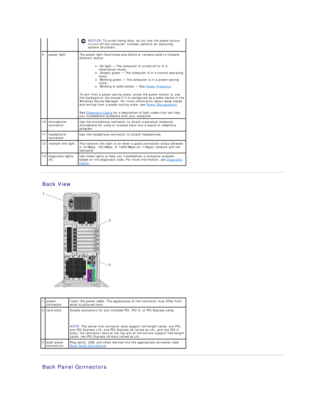
Back View
1 | power | Insert the power cable. The appearance of this connector may differ from |
|
| connector | what is pictured here. |
|
|
|
|
|
2 | card slots | Access connectors for any installed PCI, |
|
|
| NOTE: The center five connector slots support |
|
|
| one PCI Express x16, one PCI Express x8 (wired as x4), and two |
|
|
| slots; the connector slots at the top and at the bottom support |
|
|
| cards: two PCI Express x8 slots (wired as x4). |
|
|
|
|
|
3 | back panel | Plug serial, USB, and other devices into the appropriate connector (see |
|
| connectors | Back Panel Connectors). |
|
|
|
|
|
|
|
|
|