4.If a graphics riser card is installed, remove it:
a.Remove its four screws.
b.Disconnect its power cable.
c.Move it slightly up and to the right at an angle to free it from the card fan and the
d.Set the riser aside.
5.Loosen the captive thumbscrews that secure the memory shroud and lift to remove it from the computer.
6.Disconnect the speaker cable from the system board.
7.Disconnect the front fan and the card fan from the system board.
8.Unscrew the two screws that hold the processor and card fan case in place and lift it away from the computer.
9.Disconnect the
NOTICE: Carefully note the routing of each cable before you disconnect it, so that you are sure to
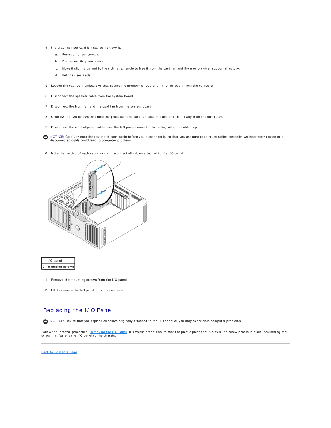
10. Note the routing of each cable as you disconnect all cables attached to the I/O panel.
1I/O panel
2mounting screws
11.Remove the mounting screws from the I/O panel.
12.Lift to remove the I/O panel from the computer.
Replacing the I/O Panel
NOTICE: Ensure that you replace all cables originally attached to the I/O panel or you may experience computer problems.
Follow the removal procedure (Removing the I/O Panel) in reverse order. Ensure that the plastic piece that fits over the screw hole is in place, secured by the screw that fastens the I/O panel to the chassis.