If you insert the module correctly, the securing clips snap into the cutouts at each end of the module.
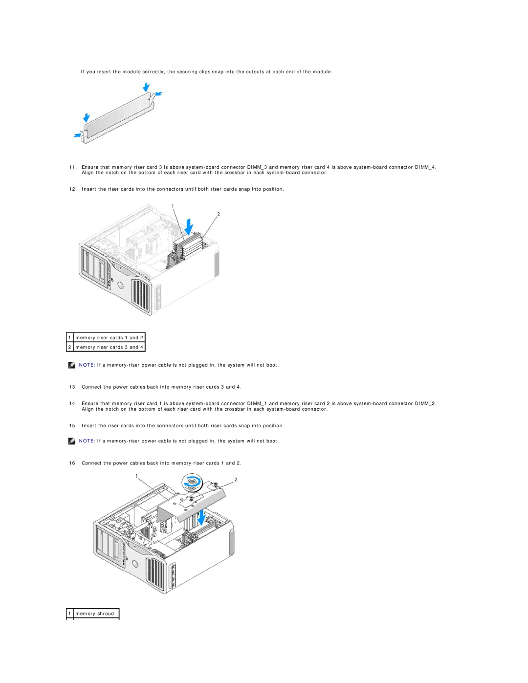
11.Ensure that memory riser card 3 is above
12.Insert the riser cards into the connectors until both riser cards snap into position.
1memory riser cards 1 and 2
2memory riser cards 3 and 4
NOTE: If a
13.Connect the power cables back into memory riser cards 3 and 4.
14.Ensure that memory riser card 1 is above
15.Insert the riser cards into the connectors until both riser cards snap into position.
NOTE: If a
16. Connect the power cables back into memory riser cards 1 and 2.
![]() 1
1 ![]() memory shroud
memory shroud