1power connectors (4)
2memory connectors (4)
3securing clips (2)
4.Disconnect the power cable from memory riser card 1 and 2.
5.Grasp the memory riser card 1 at each corner and lift memory riser card 1 and attached card 2 from the DIMM_1 and DIMM_2 slots on the system board.
If a card is difficult to remove, gently ease it back and forth to remove it from the connector.
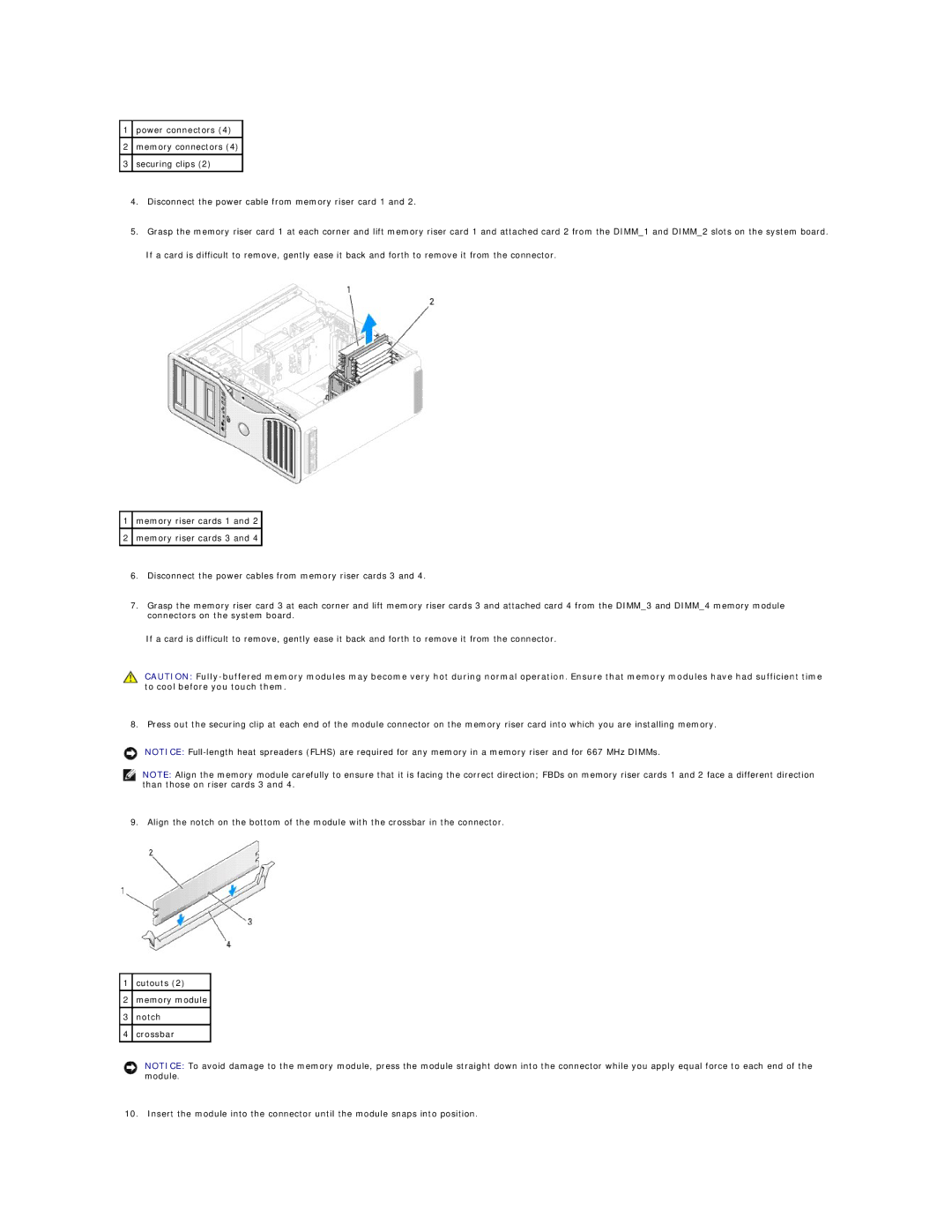
1memory riser cards 1 and 2
2memory riser cards 3 and 4
6.Disconnect the power cables from memory riser cards 3 and 4.
7.Grasp the memory riser card 3 at each corner and lift memory riser cards 3 and attached card 4 from the DIMM_3 and DIMM_4 memory module connectors on the system board.
If a card is difficult to remove, gently ease it back and forth to remove it from the connector.
CAUTION:
8. Press out the securing clip at each end of the module connector on the memory riser card into which you are installing memory.
NOTICE:
NOTE: Align the memory module carefully to ensure that it is facing the correct direction; FBDs on memory riser cards 1 and 2 face a different direction than those on riser cards 3 and 4.
9. Align the notch on the bottom of the module with the crossbar in the connector.
1cutouts (2)
2memory module
3notch
4crossbar
NOTICE: To avoid damage to the memory module, press the module straight down into the connector while you apply equal force to each end of the module.
10. Insert the module into the connector until the module snaps into position.