Introduction
Epsilon Indexing Drives
The Epsilon
The use of
The Epsilon drives can be quickly configured to many applications in less than 5 minutes with Emerson Control Techniques PowerTools Pro v4.01 software on a PC running Windows® 98, NT 4.0, 2000, ME or XP.
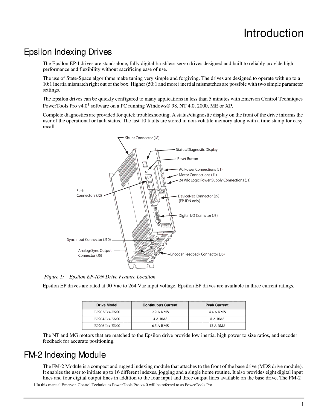
Complete diagnostics are provided for quick troubleshooting. A status/diagnostic display on the front of the drive informs the user of the operational or fault status. The last 10 faults are stored in
| Shunt Connector (J8) | |
| Status/Diagnostic Display | |
| Reset Button | |
| AC Power Connections (J1) | |
| Motor Connections (J1) | |
| 24 Vdc Logic Power Supply Connections (J1) | |
Serial |
| |
Connectors (J2) | DeviceNet Connector (J9) | |
| ||
| Digital I/O Connctor (J3) | |
| ||
| ||
| SN 0610E014 | |
Sync Input Connector (J10) |
| |
Analog/Sync Output | Encoder Feedback Connector (J6) | |
Connector (J5) | ||
|
Figure 1: Epsilon EP-IDN Drive Feature Location
Epsilon EP drives are rated at 90 Vac to 264 Vac input voltage. Epsilon EP drives are available in three current ratings.
Drive Model | Continuous Current | Peak Current |
2.2 A RMS | 4.4 A RMS | |
|
|
|
4 A RMS | 8 A RMS | |
|
|
|
6.5 A RMS | 13 A RMS | |
|
|
|
The NT and MG motors that are matched to the Epsilon drive provide low inertia, high power to size ratios, and encoder feedback for accurate positioning.
FM-2 Indexing Module
The
1.In this manual Emerson Control Techniques PowerTools Pro v4.0 will be referred to as PowerTools Pro.
1
