User Defined Motors
At a certain point in the test it will be necessary to manually rotate the motor through an integral number of revolutions. This can only be done if the motor shaft and housing are marked in some way so that the motor can be aligned to a specific position. A disk or pulley can be installed during that portion of the test to make this alignment more precise.
The four tests are Rotation test, Torque test, Commutation test and Velocity test. Each test builds on the last. It is important to perform the tests in the order given.
Note
Do not attempt to perform a test if you were not able to get the proceeding test to work.
Rotation Test
This test verifies that the encoder has been correctly interfaced to the drive.
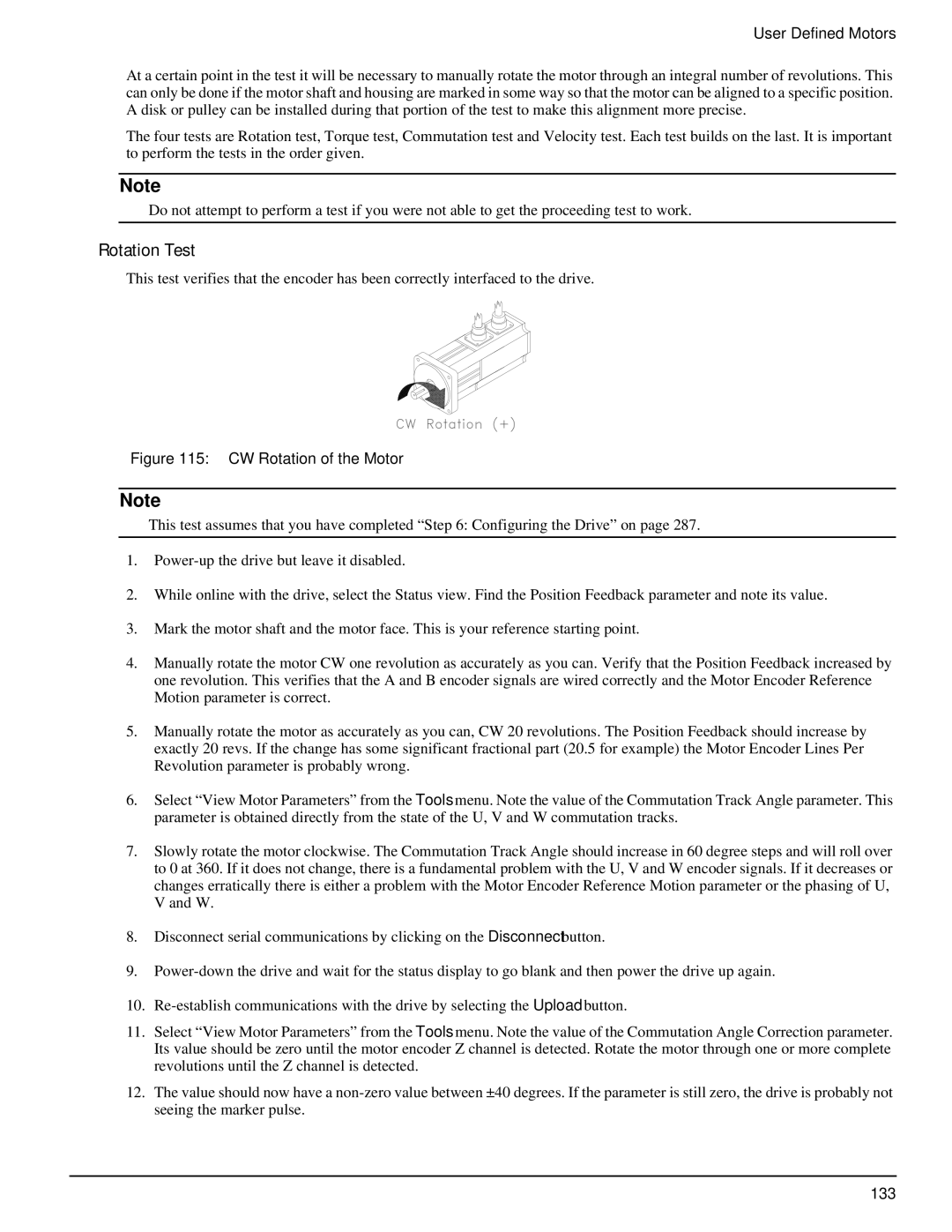
Figure 115: CW Rotation of the Motor
Note
This test assumes that you have completed “Step 6: Configuring the Drive” on page 287.
1.
2.While online with the drive, select the Status view. Find the Position Feedback parameter and note its value.
3.Mark the motor shaft and the motor face. This is your reference starting point.
4.Manually rotate the motor CW one revolution as accurately as you can. Verify that the Position Feedback increased by one revolution. This verifies that the A and B encoder signals are wired correctly and the Motor Encoder Reference Motion parameter is correct.
5.Manually rotate the motor as accurately as you can, CW 20 revolutions. The Position Feedback should increase by exactly 20 revs. If the change has some significant fractional part (20.5 for example) the Motor Encoder Lines Per Revolution parameter is probably wrong.
6.Select “View Motor Parameters” from the Tools menu. Note the value of the Commutation Track Angle parameter. This parameter is obtained directly from the state of the U, V and W commutation tracks.
7.Slowly rotate the motor clockwise. The Commutation Track Angle should increase in 60 degree steps and will roll over to 0 at 360. If it does not change, there is a fundamental problem with the U, V and W encoder signals. If it decreases or changes erratically there is either a problem with the Motor Encoder Reference Motion parameter or the phasing of U, V and W.
8.Disconnect serial communications by clicking on the Disconnect button.
9.
10.
11.Select “View Motor Parameters” from the Tools menu. Note the value of the Commutation Angle Correction parameter. Its value should be zero until the motor encoder Z channel is detected. Rotate the motor through one or more complete revolutions until the Z channel is detected.
12.The value should now have a
133
