Epsilon
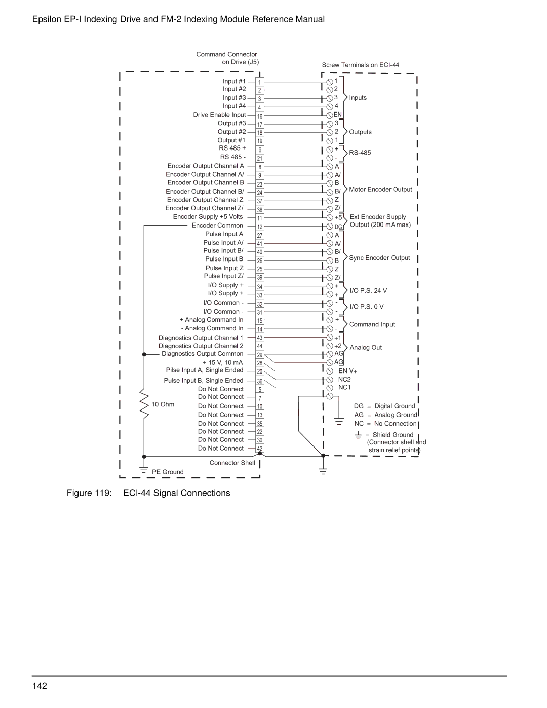
Command Connector
on Drive (J5) | |
Input #1 |
|
1 | |
Input #2 | 2 |
Input #3 | 3 |
Input #4 | 4 |
Drive Enable Input | 16 |
Output #3 | 17 |
Output #2 | 18 |
Output #1 | 19 |
RS 485 + | 6 |
RS 485 - | 21 |
Encoder Output Channel A | 8 |
Encoder Output Channel A/ | 9 |
Encoder Output Channel B | 23 |
Encoder Output Channel B/ | 24 |
Encoder Output Channel Z | 37 |
Encoder Output Channel Z/ | 38 |
Encoder Supply +5 Volts | 11 |
Encoder Common | 12 |
Pulse Input A | 27 |
Pulse Input A/ | 41 |
Pulse Input B/ | 40 |
Pulse Input B | 26 |
Pulse Input Z | 25 |
Pulse Input Z/ | 39 |
Screw Terminals on
1
2
3Inputs
4 EN 3
2Outputs
1
+ | ||
- | ||
| ||
A |
| |
A/ |
| |
B | Motor Encoder Output | |
B/ | ||
Z |
| |
Z/ |
| |
+5 | Ext Encoder Supply | |
DG | Output (200 mA max) | |
A |
| |
A/ |
| |
B/ |
|
BSync Encoder Output
Z
Z/
I/O Supply + | 34 |
I/O Supply + | 33 |
|
+
+
I/O P.S. 24 V
I/O Common - | 32 |
I/O Common - | 31 |
-
-
I/O P.S. 0 V
+ Analog Command In | 15 |
+
- Analog Command In | 14 |
-
Command Input
Diagnostics Output Channel 1 |
| 43 | |||||
Diagnostics Output Channel 2 |
| 44 | |||||
| Diagnostics Output Common | 29 | |||||
| |||||||
|
| + 15 V, 10 mA |
|
|
| 28 | |
|
|
|
|
| |||
| Pilse Input A, Single Ended |
|
|
|
| 20 | |
|
|
| |||||
| Pulse Input B, Single Ended |
|
|
|
| 36 | |
|
|
| |||||
|
| Do Not Connect |
|
|
|
| 5 |
|
|
|
|
| |||
10 Ohm | Do Not Connect |
|
|
|
| 7 | |
|
|
| |||||
Do Not Connect |
|
|
|
| 10 | ||
|
| ||||||
|
| Do Not Connect |
|
|
|
| 13 |
|
|
|
| ||||
|
| Do Not Connect |
|
|
| 35 | |
|
|
|
| ||||
|
| Do Not Connect |
|
|
| 22 | |
|
|
|
| ||||
|
| Do Not Connect |
|
|
| 30 | |
|
|
|
| ||||
|
| Do Not Connect |
|
|
| 42 | |
|
|
|
| ||||
Connector Shell
PE Ground
+1 |
|
+2 | Analog Out |
AG |
|
AG
EN V+
NC2
NC1
DG = Digital Ground
AG = Analog Ground
NC = No Connection
= Shield Ground (Connector shell and strain relief points)
