Epsilon
•Position Feedback
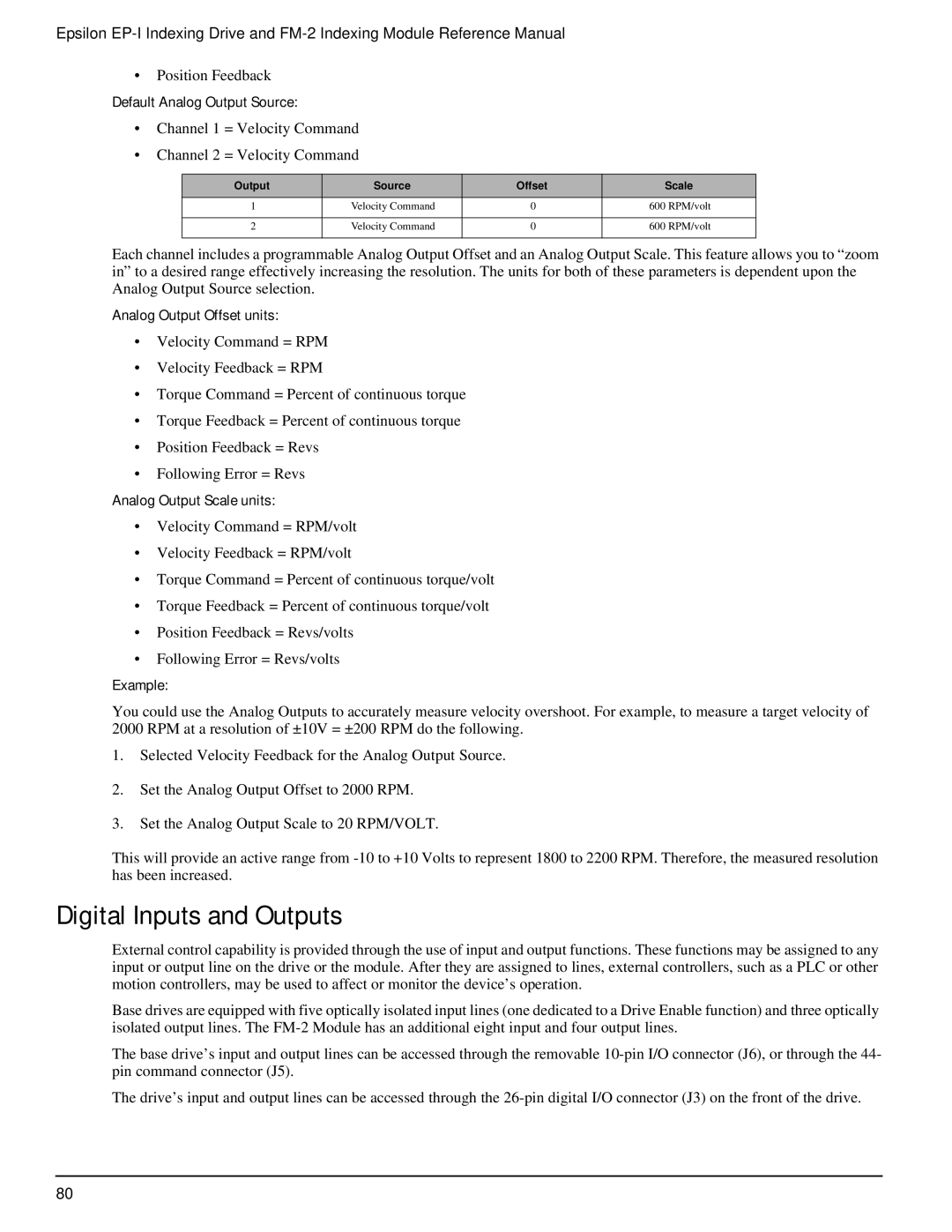
Default Analog Output Source:
•Channel 1 = Velocity Command
•Channel 2 = Velocity Command
Output | Source | Offset | Scale |
1 | Velocity Command | 0 | 600 RPM/volt |
|
|
|
|
2 | Velocity Command | 0 | 600 RPM/volt |
|
|
|
|
Each channel includes a programmable Analog Output Offset and an Analog Output Scale. This feature allows you to “zoom in” to a desired range effectively increasing the resolution. The units for both of these parameters is dependent upon the Analog Output Source selection.
Analog Output Offset units:
•Velocity Command = RPM
•Velocity Feedback = RPM
•Torque Command = Percent of continuous torque
•Torque Feedback = Percent of continuous torque
•Position Feedback = Revs
•Following Error = Revs
Analog Output Scale units:
•Velocity Command = RPM/volt
•Velocity Feedback = RPM/volt
•Torque Command = Percent of continuous torque/volt
•Torque Feedback = Percent of continuous torque/volt
•Position Feedback = Revs/volts
•Following Error = Revs/volts
Example:
You could use the Analog Outputs to accurately measure velocity overshoot. For example, to measure a target velocity of 2000 RPM at a resolution of ±10V = ±200 RPM do the following.
1.Selected Velocity Feedback for the Analog Output Source.
2.Set the Analog Output Offset to 2000 RPM.
3.Set the Analog Output Scale to 20 RPM/VOLT.
This will provide an active range from
Digital Inputs and Outputs
External control capability is provided through the use of input and output functions. These functions may be assigned to any input or output line on the drive or the module. After they are assigned to lines, external controllers, such as a PLC or other motion controllers, may be used to affect or monitor the device’s operation.
Base drives are equipped with five optically isolated input lines (one dedicated to a Drive Enable function) and three optically isolated output lines. The
The base drive’s input and output lines can be accessed through the removable
The drive’s input and output lines can be accessed through the
80