Epsilon
Switching Frequency Group (FM-2 only)
Switching Frequency (FM-2 Only)
“Switching Frequency” is used to select the Drive Module switching frequency. There are two switching frequencies, 5 KHz (default) and 10 KHz. When using 10 KHz the Drive Module current rating will be derated.
Drive Encoder Output Group
Encoder Output Scaling Check Box
Select this check box to enable the Encoder Scaling parameter of the Drive Encoder Output.
Encoder Scaling
This parameter defines the encoder resolution (lines per revolution) of the drive’s encoder output. This feature allows the user to change the drive encoder output resolution in increments of 1 line per revolution up to the density of the encoder in the motor. If the Encoder Output Scaling parameter is set to a value higher than the motor encoder density, the drive encoder output density will equal that of the motor encoder. The default is to the motor encoder density.
Positive Direction Group
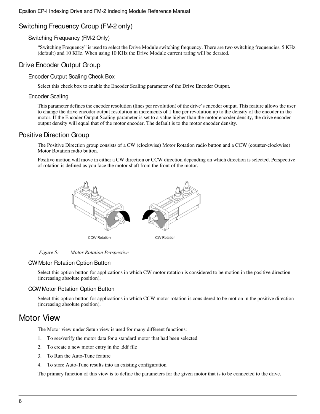
The Positive Direction group consists of a CW (clockwise) Motor Rotation radio button and a CCW
Positive motion will move in either a CW direction or CCW direction depending on which direction is selected. Perspective of rotation is defined as you face the motor shaft from the front of the motor.
Figure 5: Motor Rotation Perspective
CW Motor Rotation Option Button
Select this option button for applications in which CW motor rotation is considered to be motion in the positive direction (increasing absolute position).
CCW Motor Rotation Option Button
Select this option button for applications in which CCW motor rotation is considered to be motion in the positive direction (increasing absolute position).
Motor View
The Motor view under Setup view is used for many different functions:
1.To see/verify the motor data for a standard motor that had been selected
2.To create a new motor entry in the .ddf file
3.To Run the
4.To store
The primary function of this view is to define the parameters for the given motor that is to be connected to the drive.
6
