|
| FN10 Panels |
| Table | |
|
|
|
LED |
| Meaning |
|
|
|
Link (upper level of |
| On – Indicates the link is good. |
port LEDs) |
| Off – Indicates there is no link. |
|
|
|
Status (lower level |
| On/Blinking – Indicates you are monitoring the port for |
of port LEDs) |
| a selected segment status condition. |
|
| Off – Indicates you are not monitoring the port. |
|
|
|
Segment Status |
|
|
TX |
| On – Indicates you are monitoring Transmit (TX) |
|
| activity on all ports. |
RX |
| On – Indicates you are monitoring Receive (RX) |
|
| activity on all ports. |
Act |
| On – Indicates you are monitoring Transmit (TX) and |
|
| Receive (RX) activity on all ports. |
Col |
| On – Indicates you are monitoring packet collision on |
|
| all ports. |
Usr |
| On – Indicates you are monitoring transmission and |
|
| receive errors on all ports. |
|
|
|
Ready |
| On – Indicates the FN10 is operational. |
|
| Blinking – Indicates the FN10 is running |
|
| diagnostics. |
|
| Off – Indicates the FN10 is |
|
|
|
Pwr |
| On – Indicates the FN10 is receiving power and the |
|
| voltage is within the acceptable range. |
|
| Off – Indicates the FN10 is not receiving power. |
|
|
|
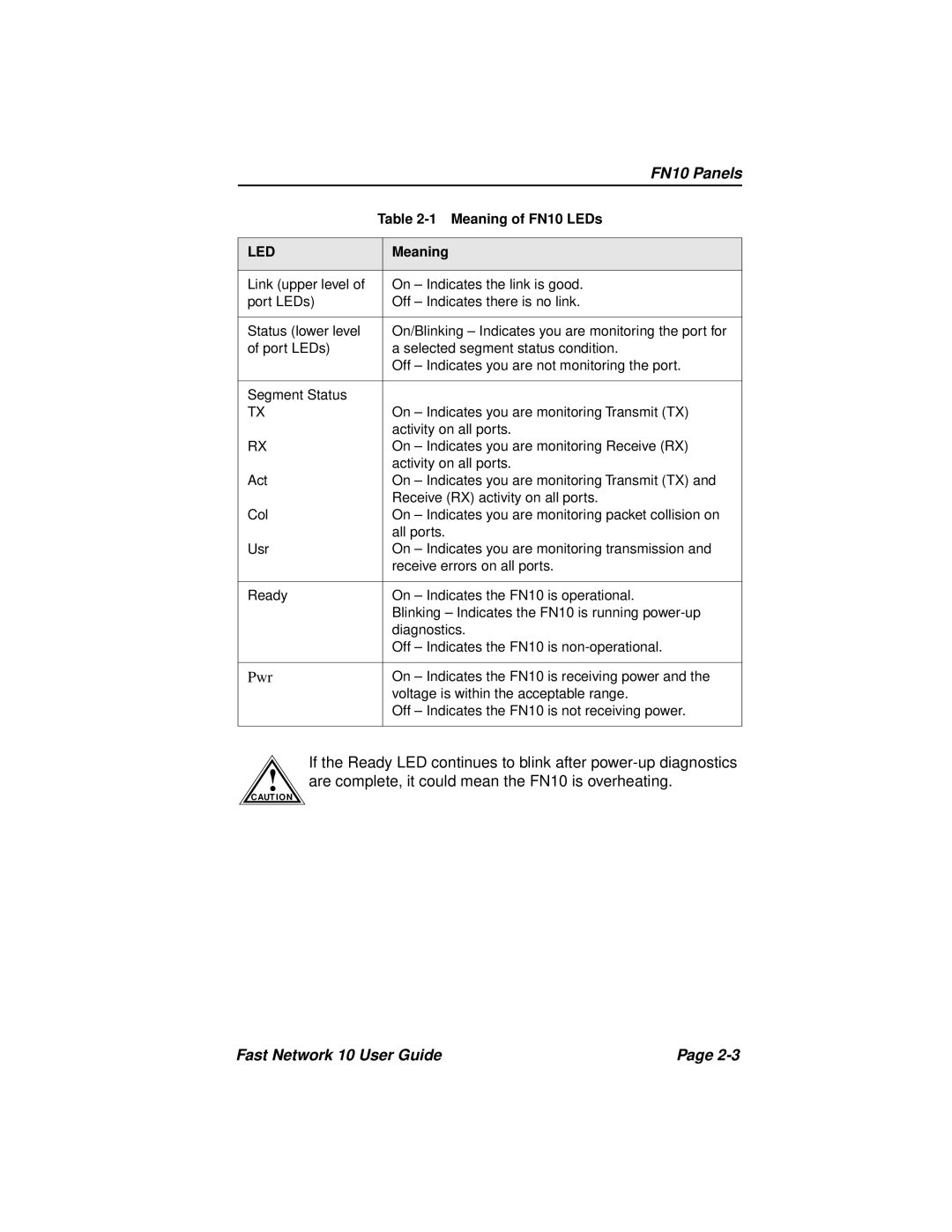
If the Ready LED continues to blink after
!are complete, it could mean the FN10 is overheating.
C AUT IO N
Fast Network 10 User Guide | Page |
