Chapter 2: Unpacking and Installing Your FN10
|
|
|
|
|
|
|
|
|
|
|
|
|
|
|
|
|
|
|
|
|
|
|
|
| Segment Status |
|
| |
|
|
|
|
|
|
|
|
|
|
|
|
|
|
|
|
|
|
|
|
|
|
|
| TX |
|
|
| |
|
|
|
|
|
|
|
|
|
|
|
|
|
|
|
|
|
|
|
|
|
|
|
|
| RX | Select | Reset Ready |
|
|
|
|
|
|
|
|
|
|
|
|
|
| Link |
|
|
|
|
|
|
|
|
|
|
| Act |
|
|
|
|
|
| 3X |
|
|
|
|
|
|
|
|
| 1 |
|
|
|
|
|
|
|
|
|
| Usr | Col |
|
|
|
AUI 1 | X | 2X | 4X | 5X | 6X | 7X | 8X | 9X | 10X | 11X | 12X | 2 | 3 | 4 | 5 | 6 | 7 | 8 | 9 10 11 12 | A | B |
|
| Pwr | NMS Port | |||
Ethernet Attachment | RJ45 Ethernet |
| |
Unit Interface (AUI) Port | Status LEDs and Buttons | ||
Crossover Ports |
FN10-24
13X | 14X | 15X | 16X | 17X | 18X | 19X | 20X | 21X | 22X | 23X | 24X | 13 14 15 16 17 18 | 19 20 21 22 23 24 |
|
|
|
|
|
|
|
|
|
|
| Link |
| Segment Status |
|
|
|
|
|
|
|
|
|
|
|
|
| TX |
|
|
|
|
|
|
|
|
|
|
|
|
| RX Select |
|
|
|
|
|
|
|
|
|
|
| Link |
| Act |
|
| 3X |
|
|
|
|
|
|
|
|
|
| Col |
|
|
|
|
|
|
|
|
|
|
| 1 2 3 4 5 6 | 7 8 9 10 11 12 A B Usr |
Reset Ready
AUI 1
X | 2X | 4X | 5X | 6X | 7X | 8X | 9X | 10X | 11X | 12X |
Pwr
NMS Port
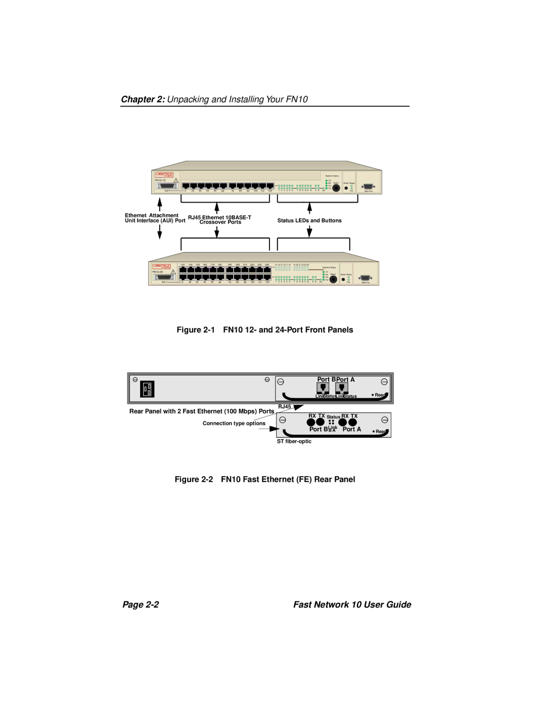
Figure 2-1 FN10 12- and 24-Port Front Panels
Port BPort A
LinkStatusLinkStatus ![]() Ready
Ready
Rear Panel with 2 Fast Ethernet (100 Mbps) Ports
Connection type options
RJ45
RX TX Status RX TX
Port BLink Port A
B A![]() Ready
Ready
ST
Figure 2-2 FN10 Fast Ethernet (FE) Rear Panel
Page | Fast Network 10 User Guide |
