Chapter 2: Unpacking and Installing Your FN10
Table 2-2 describes the FN10 buttons.
| Table | Description of FN10 Buttons | |
|
|
| |
Button | Function |
| |
|
| ||
| Cycles through the Segment Status options (TX, RX, Act, | ||
Select | Col, and Usr) for all ports. The lower port status LEDs of the | ||
ports you are monitoring are activated based on what | |||
| |||
| function you chose with the Select button. | ||
|
| ||
Reset | Restarts the FN10. | ||
|
|
| |
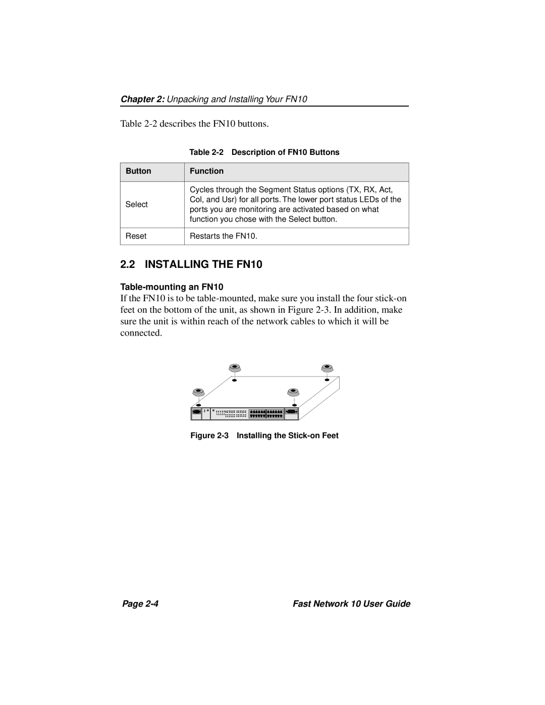
2.2 INSTALLING THE FN10
If the FN10 is to be
Figure 2-3 Installing the Stick-on Feet
Page | Fast Network 10 User Guide |