Crossover Wiring
A.5 CROSSOVER WIRING
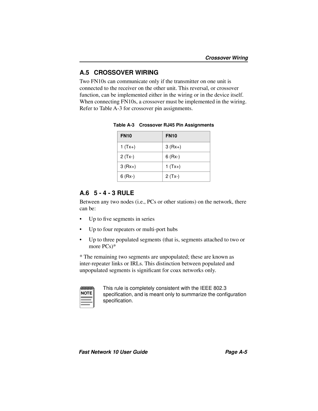
Two FN10s can communicate only if the transmitter on one unit is connected to the receiver on the other unit. This reversal, or crossover function, can be implemented either in the wiring or in the device itself. When connecting FN10s, a crossover must be implemented in the wiring. Refer to Table
Table
FN10 | FN10 | ||
|
|
|
|
1 | (Tx+) | 3 | (Rx+) |
|
|
|
|
2 | 6 | ||
|
|
|
|
3 | (Rx+) | 1 | (Tx+) |
|
|
|
|
6 | 2 | ||
|
|
|
|
A.6 5 - 4 - 3 RULE
Between any two nodes (i.e., PCs or other stations) on the network, there can be:
•Up to five segments in series
•Up to four repeaters or
•Up to three populated segments (that is, segments attached to two or more PCs)*
*The remaining two segments are unpopulated; these are known as
NOTE |
This rule is completely consistent with the IEEE 802.3 specification, and is meant only to summarize the configuration specification.
Fast Network 10 User Guide | Page |