Appendix A: Technical Specifications
| Table A-1 Pin Assignments |
| | |
Pin | | Assignmenta |
| | |
1 | | Tx+ |
| | |
2 | | Tx- |
| | |
3 | | Rx+ |
| | |
6 | | Rx- |
| | |
a.The “+” and “-” signs are used to represent the polarity of the two wires that make up each wire pair.
A.4 STRAIGHT-THROUGH WIRING
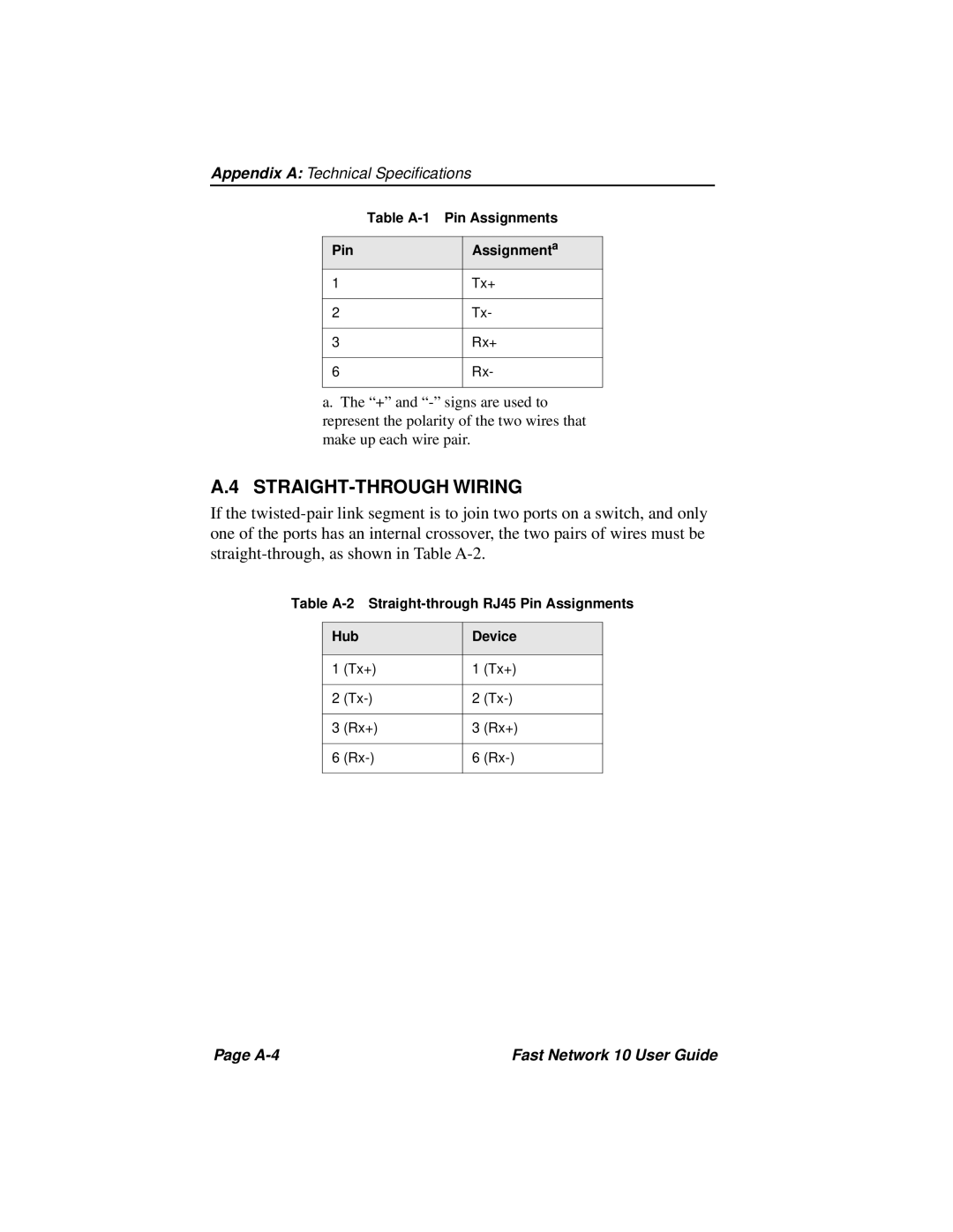
If the twisted-pair link segment is to join two ports on a switch, and only one of the ports has an internal crossover, the two pairs of wires must be straight-through, as shown in Table A-2.
Table A-2 Straight-through RJ45 Pin Assignments
Hub | Device |
| | | |
1 | (Tx+) | 1 | (Tx+) |
| | | |
2 | (Tx-) | 2 | (Tx-) |
| | | |
3 | (Rx+) | 3 | (Rx+) |
| | | |
6 | (Rx-) | 6 | (Rx-) |
| | | |
Page A-4 | Fast Network 10 User Guide |