Serial Cable Pin Assignments
A.2 SERIAL CABLE PIN ASSIGNMENTS
For a PC running a Windows terminal connected to the RS232C Network Management Port on the front panel of the FN10, the following serial cable pin assignments are required to manage the FN10 using the Local Console Manager (LCM).
PC | ||||
(female) | ||||
|
| |||
|
|
|
| |
Pin 2 | (Rx) | Pin 2 | Pin 3 | |
|
|
|
| |
Pin 3 | (Tx) | Pin 3 | Pin 2 | |
|
|
|
| |
Pin 5 | (Ground) | Pin 5 | Pin 7 | |
|
|
|
| |
A.3 10BASE-T PIN ASSIGNMENTS
An Ethernet
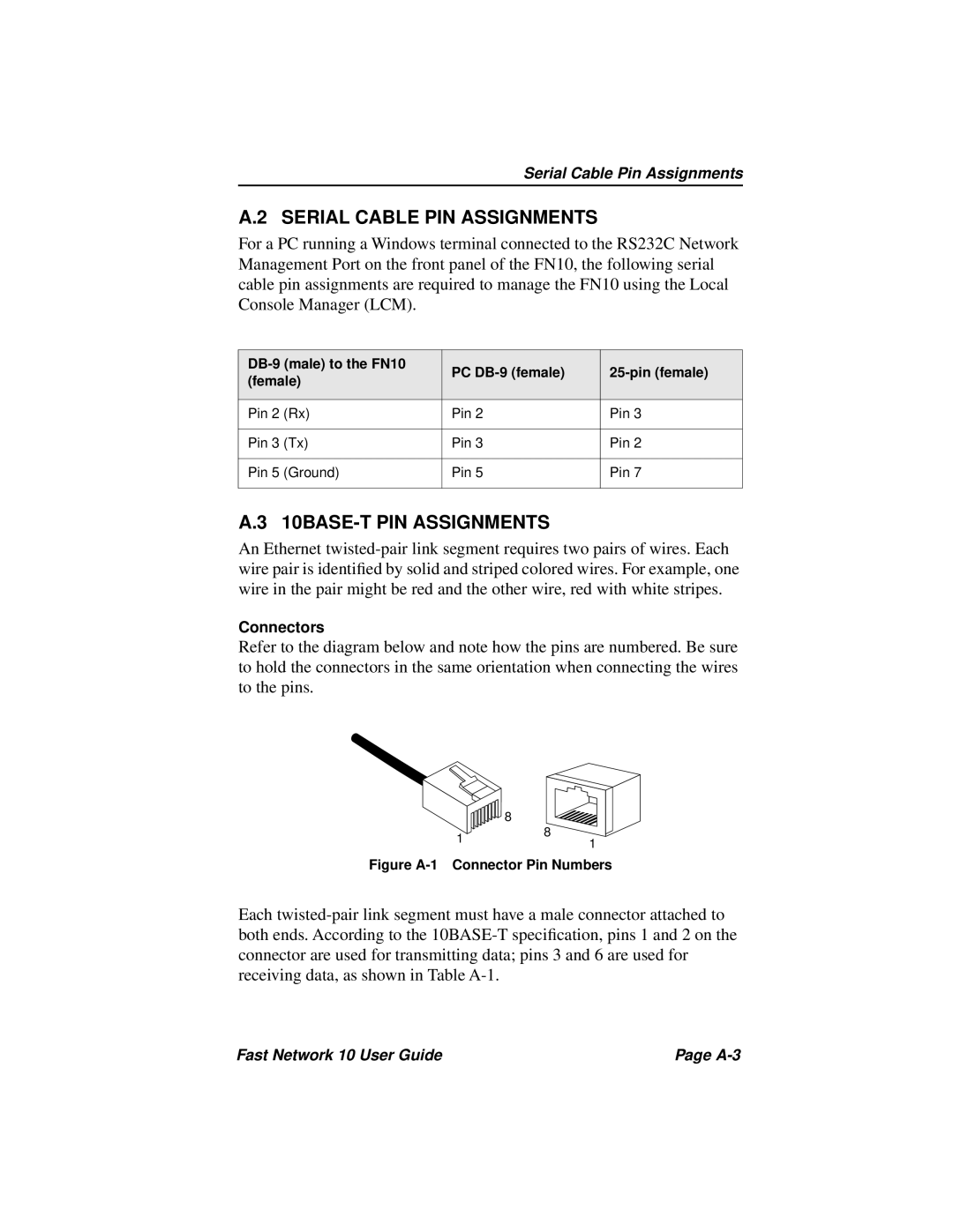
Connectors
Refer to the diagram below and note how the pins are numbered. Be sure to hold the connectors in the same orientation when connecting the wires to the pins.
| 8 | |
1 | 8 | |
1 | ||
|
Figure A-1 Connector Pin Numbers
Each
Fast Network 10 User Guide | Page |