DXP DVI
Safety Instructions English
FCC Class a Notice
Specifications Availability
Software Commands
Conventions Used in this Guide
Notifications
Contents
122
105
About this Guide
DXP DVI Series non-Pro
DXP DVI Pro Series
DXP DVI and DXP DVI Pro Series
Features
DXP Hdmi Series
DXP DVI, DXP DVI Pro, and DXP Hdmi
Rack-mountable 2U, full rack width metal enclosure
Application Diagram for a DXP 88 Hdmi
Application Diagrams
Application Diagram for a DXP 88 DVI Pro
Application Diagram for a DXP 88 DVI Non-Pro
DXP 88 DVI Pro Rear Panel
Rear Panels
DVI Connector Pin Assignments
Input connectors
Output connectors
Straight-through Cable Pin End Wire Color
Wire Color
Connections
Ethernet Connection
Remote RS232/RS422 Connector Pin Assignments
RS-232 Config port front panel
RS-232 and RS-422 Remote Connections
Remote RS232/RS422 port rear panel
Definitions
Operation
DXP Switchers Front Panel
Front Panel Controls and Indicators
Input and Output Buttons
Setting the Button Background Illumination on
Control Buttons
Configuration Port
Secondary functions
Buttons
Example of Button Labels on a DXP Front Panel
Button Icons
Creating a Configuration
Powering On
Clear All Selections
Example 1 Creating a Set of Ties
Select Input
Select Video Only
Example 2 Adding a Tie to a Set of Video Ties
Confirm the Tie
Breaking Ties
Select Audio Only
Example 3 Removing a Tie from a Set of Ties
Confirm the Tie Removal
Viewing a Configuration
Press the Esc button to clear all selections
Select an Input to View
Deselect Audio and Select Video to View Only Video Ties
Example 5 Saving a Preset
Saving and Recalling Presets
Enter Save Preset Mode
Example 6 Recalling a Preset
Enter Recall Preset Mode
O Grouping of Incompatible Video Formats
Grouping
Group #
Example 7 Grouping Inputs and Outputs
Select I/O Group Mode
Assign Inputs and Outputs to Group
Muting and Unmuting Video and Audio Outputs
Deselect I/O Group Mode
Example 8 Muting and Unmuting an Output
Mute the Outputs
Locking and Unlocking the Front Panel Executive Modes
Selecting Lock Mode 2 or Toggling Between Mode 2 and Mode
Resetting
Switching from Lock Mode 1 to Lock Mode
Resetting the System from the Front Panel
System Reset
Resetting Using the Rear Panel Reset Button
Mode Activation Result Purpose/Notes
Reset Modes Summary
Soft Resets
Toggle Background Illumination On or Off
Setting the Button Background Illumination
RS-232/RS-422 and Baud Rate Selection
Troubleshooting
Worksheet Example 1 System Equipment
Configuration Worksheets
Worksheet Example 3 Test Configuration
Worksheet Example 2 Daily Configuration
Input Sources Output Destinations
Worksheet Form
Serial Ports
SIS Configuration Control
Ethernet Port
Default IP Addresses
Ethernet Cable
Establishing an Ethernet Connection
Switcher-initiated Messages
Host-to-Switcher Instructions
Connection Timeouts
Verbose Mode
Password
Switcher Error Responses
Using the Command and Response Tables for SIS Commands
Special Characters
Symbol Definitions for DXP
SIS Commands for DXP
X1#
X1$
X2# X2$
DXP DVI, DXP DVI Pro, and DXP Hdmi DXP DVI Pro and Hdmi
Edid Table DDC Source Selection
@ *X# $
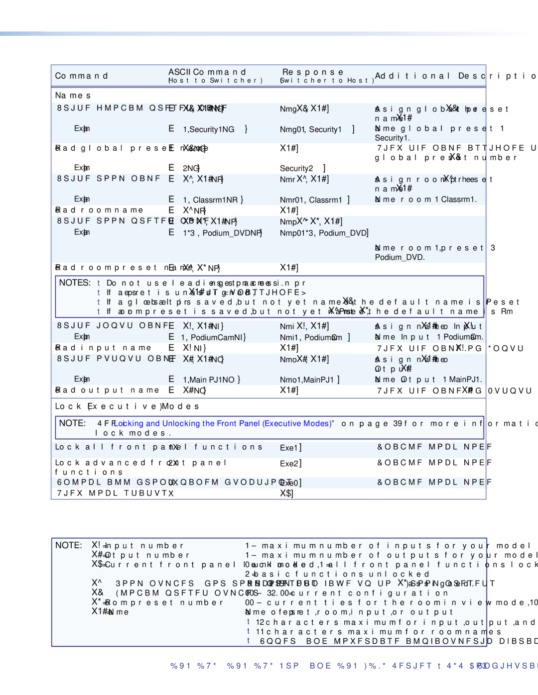
Command and Response Table for DXP SIS Commands
+Q X@ *X# %...X@ *X#
@ *%
Save, Recall, and Directly Write Global and Room Presets
Mute Commands
# B
# Z
+X& PO
+ X& P X@*X#!X@*X# % X@*X#$...X@*X#
X# ,X# , ...X# n MR Mpr X ,X# ,X# , ...X# n
X1# X ,X# ,X# , ...X# n
View Ties and Presets
+X*X* P X@*X#!X@*X#%X@*X#$...X@*X#
@X@...X@Vid
DXP 88 Hdmi
@X@...X@Aud
% X%...X% O
% X%... X%nI
Gro X% X% X%...X%n
Digital Sync Validation Processing Dsvp
2NG
X1# NG Nmg X&,X1#
X1# NR Nmr X,X1#
X* ,X1# NP Nmp X *X* ,X1#
Resets
Hdcp Authorization DXP DVI Pro and Hdmi models only
X* ZP
Information Requests
Firmware Version Queries
X1X1X1&X1*X$
X!*X1 Edid
Edid Extended Display Identification Data Commands
X1 EDIDX2
X1 . X1 = 37
X1 X1...X1n
Hdcp Query Commands
Symbol Definitions for IP-specific Commands
IP-specific SIS Commands
X3@ X3# X3$ X3%
X4#
X4$
X5#
X5$ X5%
Command and Response Table for IP-Specific SIS Commands
X4 DH
X4# X4!,X4$,X4% EM Ipe X4# X4!*X4$*X4% X4%...X4%
X4&*X4*,X4,X5,X5! CP
Cpn X4&Ccp X4*,X4,X5,X5
Installing the Software
Matrix Switchers Control Program
Using the Software
Ethernet protocol settings
Software Operation Via Ethernet
Baud Rate Pop-up List
Extron Matrix Switcher Control Program Matrix Window No Ties
Sample Matrix Window with Ties
Setting Up the Matrix Window
Pop-up Window for Input 4 Containing a Caption
Managing Ties
Matrix Window with Pop-up Information on Audio Input
IP Settings/Options Window
IP Setup
Setting the IP address
Setting the Extron name or descriptor
Setting the gateway IP address
Setting the date
Setting the subnet mask
Hardware Address field
Enabling and disabling Dhcp
Setting the offset from GMT
Setting the local time
Setting the administrator password
Sync Time to PC button
Setting the user password
Setting the mail server IP address
Setting the mail server domain name
Typical DXP E-mail
Entering e-mail addressee information
Updating the Firmware
Select Files to Upload Window with Firmware File Selected
Html Files List Window
Uploading Html Files
Window Buttons, Menus, and Trash Can Right Column
Window Menus
File menu
Devices Window
Tools menu
Channel Mute Settings Window
Edid Record Viewer
Uploading Html Files on
Names for Presets Window
Input/Output Groups Window
Room Configuration Window
Ties Shown as Lines
Preferences menu
Ties Shown as Crosspoints
O Boxes Containing the Input and Output Numbers
Master-Reset button
Using Emulation Mode
Help menu
IP Connection
Selecting an Emulation File
Creating Button Labels
Using the Matrix Switcher Help File
Button Label Generator Window
Using the Button Label Generator
Replacing a Button Label
Replacing Button Labels
Blank Button Labels
Html Operation
Accessing the Web Pages
Special Characters
Example of a Network Password Dialog Box
System Status
Status Tab
Dsvp and Hdcp Page for the DXP DVI Pro and DXP Hdmi
Dsvp and Hdcp
System Settings
Configuration Tab
Unit Name field
IP Settings Fields
Date/Time Settings Fields
Date/Time Settings Fields
Passwords
Entering a password
Clearing a password
Mail IP Address field
Email Settings
Smtp Authorization Required fields
Domain Name field
Email address fields
Email Options Menu on the Email Settings
Firmware Upgrade
Choose File Window with a Firmware File Selected
Uploading Files
File Management Tab
Other File Management Activities
Adding a Directory
Set and View Ties
Control Tab
Pop-up Field Providing Formation About a Button Tie
Global Presets
Saving a preset
Recalling a preset
Included Part Replacement Part Number
Part Numbers and Accessories
Models
Included Parts
Optional Accessories
Mounting the Switcher
Cables and Adapters
UL Guidelines for Rack Mounting
Rack Mounting the DXP to a 19-inch Rack
Rack Mounting Procedure
IP Addressing
What is an IP Address?
Choosing IP Addresses
Class Name Valid Address Range Identifier Arrangement
Pinging for the IP Address
Subnet Mask
Ping to determine Extron IP address
Class Name Subnet Mask
Connecting as a Telnet Client
Ping to determine web IP address
Starting Telnet
Connecting to the DXP Open command
Operating using Telnet
Gateways
Subnetting, a Primer
Local and remote devices
IP addresses and octets
Determining whether devices are on the same subnet
Subnet masks and octets
Unmasked octets are compared indicated by ? in figure
Masked octets are not compared indicated by n in figure
Extron Warranty