2 |
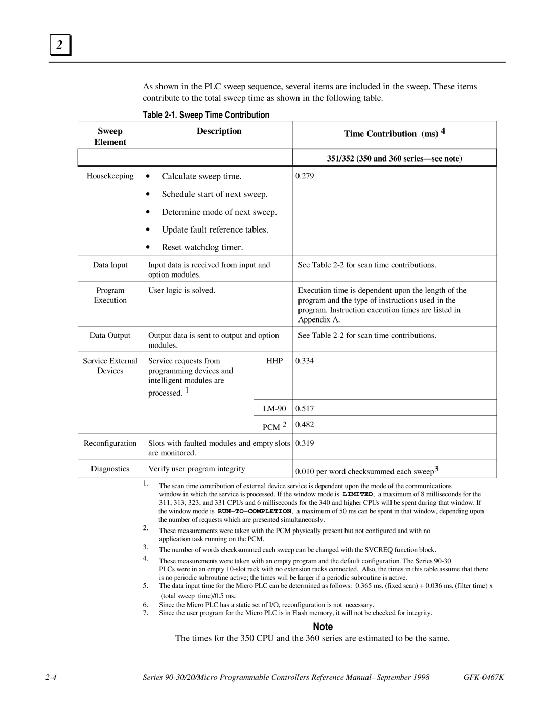
As shown in the PLC sweep sequence, several items are included in the sweep. These items contribute to the total sweep time as shown in the following table.
Table 2-1. Sweep Time Contribution
Sweep |
| Description | Time Contribution (ms) 4 |
Element |
|
|
|
|
|
|
|
|
|
| 351/352 (350 and 360 |
|
|
|
|
|
|
| |
Housekeeping ∙ | Calculate sweep time. | 0.279 | |
∙Schedule start of next sweep.
∙Determine mode of next sweep.
∙Update fault reference tables.
∙Reset watchdog timer.
Data Input | Input data is received from input and | See Table | |
| option modules. |
|
|
|
|
|
|
Program | User logic is solved. |
| Execution time is dependent upon the length of the |
Execution |
|
| program and the type of instructions used in the |
|
|
| program. Instruction execution times are listed in |
|
|
| Appendix A. |
|
|
|
|
Data Output | Output data is sent to output and option | See Table | |
| modules. |
|
|
|
|
|
|
Service External | Service requests from | HHP | 0.334 |
Devices | programming devices and |
|
|
| intelligent modules are |
|
|
| processed. 1 |
|
|
|
| 0.517 | |
|
|
|
|
|
| PCM 2 | 0.482 |
Reconfiguration | Slots with faulted modules and empty slots | 0.319 | |
| are monitored. |
|
|
|
|
|
|
Diagnostics | Verify user program integrity |
| 0.010 per word checksummed each sweep3 |
1.The scan time contribution of external device service is dependent upon the mode of the communications
window in which the service is processed. If the window mode is LIMITED, a maximum of 8 milliseconds for the 311, 313, 323, and 331 CPUs and 6 milliseconds for the 340 and higher CPUs will be spent during that window. If the window mode is
2.These measurements were taken with the PCM physically present but not configured and with no application task running on the PCM.
3.The number of words checksummed each sweep can be changed with the SVCREQ function block.
4.These measurements were taken with an empty program and the default configuration. The Series
PLCs were in an empty
5.The data input time for the Micro PLC can be determined as follows: 0.365 ms. (fixed scan) + 0.036 ms. (filter time) x
(total sweep time)/0.5 ms.
6.Since the Micro PLC has a static set of I/O, reconfiguration is not necessary.
7.Since the user program for the Micro PLC is in Flash memory, it will not be checked for integrity.
Note
The times for the 350 CPU and the 360 series are estimated to be the same.
Series |