4 |
ONDTR
A retentive
When the ONDTR first receives power flow, it starts accumulating time (current value). When this timer is encountered in the ladder logic, its current value is updated.
Note
If multiple occurrences of the same timer with the same reference address are enabled during a CPU sweep, the current values of the timers will be the same.
When the current value equals or exceeds the preset value PV, output Q is energized. As long as the timer continues to receive power flow, it continues accumulating until the maximum value is reached. Once the maximum value is reached, it is retained and output Q remains energized regardless of the state of the enable input.
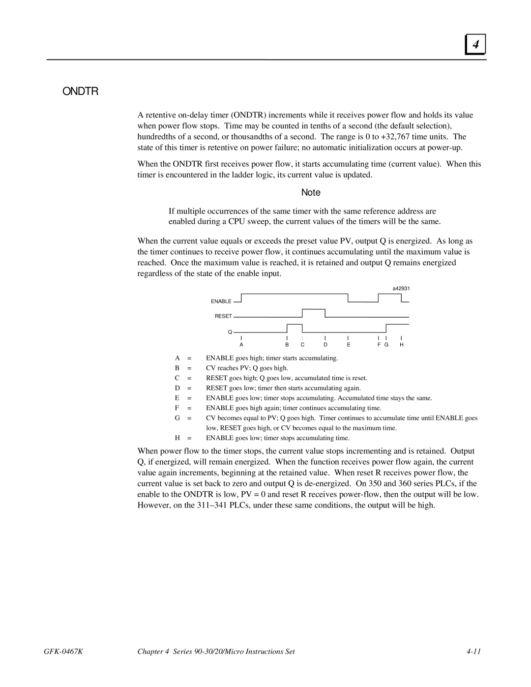
a42931
ENABLE ![]()
RESET ![]()
Q
AB C D EF G H
A= ENABLE goes high; timer starts accumulating.
B= CV reaches PV; Q goes high.
C= RESET goes high; Q goes low, accumulated time is reset.
D= RESET goes low; timer then starts accumulating again.
E= ENABLE goes low; timer stops accumulating. Accumulated time stays the same.
F= ENABLE goes high again; timer continues accumulating time.
G= CV becomes equal to PV; Q goes high. Timer continues to accumulate time until ENABLE goes low, RESET goes high, or CV becomes equal to the maximum time.
H= ENABLE goes low; timer stops accumulating time.
When power flow to the timer stops, the current value stops incrementing and is retained. Output Q, if energized, will remain energized. When the function receives power flow again, the current value again increments, beginning at the retained value. When reset R receives power flow, the current value is set back to zero and output Q is
Chapter 4 Series |